• Our new ticketing site is now live! Using either this or the original site (both powered by TrainSplit) helps support the running of the forum with every ticket purchase! Find out more and ask any questions/give us feedback in this thread!

Overhead Line Power Capacity

Status
Not open for further replies.
Joined
5 Aug 2015
Messages
896
Location
Norfolk
That isn't good, especially given it's on the busiest part of the ECML.
Always seemed strange to me that the project didn't upgrade anything in the King's Cross area since the vast, vast majority of electric trains on the ecml pass through this area (all the TL and GN trains). Then again the feeding distance to Wood Green is scarcely more than 5 miles (132/25 supplies normally can do ~18miles) and the top speeds aren't that high.
It seems that the 25kV supply is derived from a single phase which causes phase imbalances as the load is on one phase so the other two phases are at a significantly lower load.
Indeed, this is the original deal with the devil for the 25kV 50Hz system as it was first developed in the 1950s. On the one hand you get fewer total substations and far less distribution equipment to deal with (as opposed to earlier forms of electrification) but on the downside you have to have neutral sections to separate OLE sections are not only on different supplies but fully 120° out of phase, and you are an ever increasing burden on the electricity supply industry. (There are quite a few other pros/cons to choosing the 25kV system I could ramble on about) I believe adjacent feeder stations typically draw from different phase combinations to try and give a vague semblance of balance.
I presume traditionally they had a 132kV/25kV transformer on one phase which they could get away with up to a certain power level, but increasing the power will take it beyond acceptable limits.
When the earliest 25kV lines in the 1960-70s were coming about, there wasn't as much in the way of 275-400kV supergrid lines. This meant that the 132kV network (from ~the 1930s) was still being used for long distance transmission duties so the unbalanced railway load was better smoothed over. But over time the 132kV lines were relegated totally to regional distribution carrying lighter loads so the burden of railway supplies became more apparent. And in the long run generation has gone from 100% turbines to now quite mixed with power electronics, so the problem of railway connections is only more serious. I think this is finally why power electronics are making their way onto the railway with SFCs of which ECML is a pioneer in britain.
From Rail Engineer: "SFCs work by taking a three-phase balanced load from a high-voltage transmission line, converting it to DC and then to a single phase 25kV OLE supply. As a result, their use does not affect the balance between the transmission line’s three phases. Hence, they can be fed from a local distribution network’s 33kV supply." https://www.railengineer.co.uk/static-frequency-converters-improving-the-25kv/
I've heard that SFCs or inverters more generally have been used for decades in other countries but I don't know to what extent it's been used on single-phase 25kV 50-60Hz systems? Power electronics seem to be associated with the 15kV 16.7Hz standard used in Germany, Austria, Switzerland and Scandinavia. Those systems have always needed some way to change to their nonstandard frequency from the 3-phase 50Hz grid. And because of that they still have quite a few railway power stations or large scale inverter plants. These feed a traction power network at between 55kV and 132kV all at 16.7Hz single phase spanning all the German speaking countries.
 
Sponsor Post - registered members do not see these adverts; click here to register, or click here to log in
R

RailUK Forums

HSTEd

Veteran Member
Joined
14 Jul 2011
Messages
20,297
Power electronics are now cheap, so even grid frequency railway electrification systems can benefit from them.

I suppose the ultimate result of proceeding in this direction is a railway where there are no phase breaks and all 25kV overhead wiring is operated in parallel. Probably using autotransformer feeding to allow more feeders to cooperate on any given load.

Of course I do wonder what would happen in voltage terms if 25kV didn't have the advantage of a huge global install base. I think 50kV would probably win out if we started from scratch now.
 

ryan125hst

Established Member
Joined
2 Jun 2011
Messages
1,327
Location
Retford
Always seemed strange to me that the project didn't upgrade anything in the King's Cross area since the vast, vast majority of electric trains on the ecml pass through this area (all the TL and GN trains). Then again the feeding distance to Wood Green is scarcely more than 5 miles (132/25 supplies normally can do ~18miles) and the top speeds aren't that high.
Agreed, it's definitely strange given it must be the area of highest load.
I've heard that SFCs or inverters more generally have been used for decades in other countries but I don't know to what extent it's been used on single-phase 25kV 50-60Hz systems? Power electronics seem to be associated with the 15kV 16.7Hz standard used in Germany, Austria, Switzerland and Scandinavia. Those systems have always needed some way to change to their nonstandard frequency from the 3-phase 50Hz grid. And because of that they still have quite a few railway power stations or large scale inverter plants. These feed a traction power network at between 55kV and 132kV all at 16.7Hz single phase spanning all the German speaking countries.
Power electronics are now cheap, so even grid frequency railway electrification systems can benefit from them.
Are they installing SFC's on all new electrification programs in the UK now, such as HS2?

I suppose the ultimate result of proceeding in this direction is a railway where there are no phase breaks and all 25kV overhead wiring is operated in parallel. Probably using autotransformer feeding to allow more feeders to cooperate on any given load.

Of course I do wonder what would happen in voltage terms if 25kV didn't have the advantage of a huge global install base. I think 50kV would probably win out if we started from scratch now.
Neutral sections will still be needed for isolation purposes though to allow certain parts of the OLE to be powered down for maintenance.

What clearances are needed for 50kV?
 

Richard123

Member
Joined
11 Nov 2018
Messages
110
Location
Rugby
Certainly Australia, USA, Saudi, Czech, Estonia, Latvia, Lithuania, Poland already have or are building 25kV SFCs.

Mostly new schemes within the last decade, by less "engineering heavy" infrastructure managers less constrained by their historic standards/inertia and more accountable for their business case. In the UK our grid connections for future electrification are contracted by NR long before detailed scheme development and costing of options starts in earnest, sometimes a decade ahead due to lead time for connection at 400kV. Same for HS2, for similar reasons.

France, Spain, UK are notable by their absence (ECML excepted), but all have large established engineering organisations, policy and standards.

It's easier to buy a car when you don't already have a stables, cart, processes for horse riding and a full staff of trained saddlers and blacksmiths I guess
I've heard that SFCs or inverters more generally have been used for decades in other countries but I don't know to what extent it's been used on single-phase 25kV 50-60Hz systems? Power electronics seem to be associated with the 15kV 16.7Hz standard used in Germany, Austria, Switzerland and Scandinavia. Those systems have always needed some way to change to their nonstandard frequency from the 3-phase 50Hz grid. And because of that they still have quite a few railway power stations or large scale inverter plants. These feed a traction power network at between 55kV and 132kV all at 16.7Hz single phase spanning all the German speaking countries.
 
Last edited:

Paul AC

Member
Joined
3 Aug 2025
Messages
241
Location
Timperley
Yes, SFCs have advantages where there isn't a suitable high capacity supply. However they must be more expensive in capital cost, and less efficient and require more maintenance, than the equivalently-rated transformer-only design. You need to look at the lifetime cost of the alternatives.
 
Joined
5 Aug 2015
Messages
896
Location
Norfolk
Are they installing SFC's on all new electrification programs in the UK now, such as HS2?
As Richard123 said, projects that are already some way into planning or design will already have a fairly fixed idea of what kind of grid connections are in order. I think it'd be very unlikely for HS2 or MML (if it gets uncancelled for a second time) to change specification and use SFC connections since all the grid points for 50kV AT at those sites will be well established in NG plans so it'd only offer more expense to change that specification for minimal gain. (Note that MML is/would be using 400/50kV sites to feed at 25kV in 'classic' mode because AT OLE infra was scrapped in the first round of cancellation although the grid feeds date back all the way to the initial plans when AT was the new hot trend). Any electrification being planned at the moment has a decent chance of using SFCs.
Neutral sections will still be needed for isolation purposes though to allow certain parts of the OLE to be powered down for maintenance.
Not especially. Each OLE circuit is individually controllable and all circuits are technically electrically separate (except that they meet at the busbar when powered).
1755801244626.png
In this diagram, the two lines at the bottom correspond to the "up" and "down" lines of two track plain-line. The big black rectangles are neutral sections and the diagonal lines (at each intermediate traction sectioning location (or "TSL")) are either insulated overlaps or section insulators (same function different kinds of OLE component). This is quite meaningfully different from an overhead line neutral section (aka OHNS).

A section insulator only electrically separates the circuits on either side. It cannot insulate against to AC waves 120degrees out of phase like a neutral section. Similarly no part of it is actually neutral and the train can draw power while traversing a section insulator, this is because the pantograph is allowed to bridge between the two sections which will happen for less than a second at speed. Letting a train stand still with its pantograph on a section insulator is more frowned upon, but they're such a small OLE component that this rarely is an issue (compared to OHNSs).
1755801936245.png

This is basically what a section insulator looks like top down. You can see that it keeps the circuits separate but the conductor strip of a pantograph will connect the two circuits. This is fine because they will already be connected at the busbar of the substation.
1755802158049.png
This is what they look like in real life.

Section insulators are also fitted at point work to separate OLE circuits and many of those (if it's for a siding) will have manually or remote control motorised switches to isolate that specific line. But in general, a stretch of line between any substation is fed by circuit breakers so the electrical control operator can isolate them at the flick of a switch.
 

Paul AC

Member
Joined
3 Aug 2025
Messages
241
Location
Timperley
Are those section insulators suitable for use at (say) 125 mph? The skidless version particularly looks like it would put a "hard spot" in the wiring and upset the contact wire dynamics.
 
Joined
5 Aug 2015
Messages
896
Location
Norfolk
Power electronics are now cheap, so even grid frequency railway electrification systems can benefit from them.

I suppose the ultimate result of proceeding in this direction is a railway where there are no phase breaks and all 25kV overhead wiring is operated in parallel.
They're definitely interested in this sort of thing and I reckon we'll see a trial between Hambleton Jnc and Potteric Carr to test out that capability. They may or may not conclude that synchronising the whole railway at once is a good idea, and OHNSs (although a headache at times) aren't actually that big of a deal. As @Richard123 put very well, the whole industry is built around dealing with them.
Probably using autotransformer feeding to allow more feeders to cooperate on any given load.
I think it's unlikely AT will be implemented that much in the future except for where high power is really needed like on high speed lines. For one thing you have to install a small substation with ATs every 10 or so kilometres to keep the voltage up (this is what's done on HS1), and you need to find space for another live conductor that has to have 50kV clearance to the OLE. On new-build railways this is all much less of a problem.

With that being said, I have heard that power electronics are combined with 2x25kV AT in Saudi Arabia for maximum distance between supply points.
Of course I do wonder what would happen in voltage terms if 25kV didn't have the advantage of a huge global install base. I think 50kV would probably win out if we started from scratch now.
I'd be interested to know why 25kV was picked in the first place. There might be something to be said for the size of insulators within internal components of a train. Especially for multiple units but I'm just guessing.
 

Richard123

Member
Joined
11 Nov 2018
Messages
110
Location
Rugby
They're definitely interested in this sort of thing and I reckon we'll see a trial between Hambleton Jnc and Potteric Carr to test out that capability. They may or may not conclude that synchronising the whole railway at once is a good idea, and OHNSs (although a headache at times) aren't actually that big of a deal. As @Richard123 put very well, the whole industry is built around dealing with them.

I think it's unlikely AT will be implemented that much in the future except for where high power is really needed like on high speed lines. For one thing you have to install a small substation with ATs every 10 or so kilometres to keep the voltage up (this is what's done on HS1), and you need to find space for another live conductor that has to have 50kV clearance to the OLE. On new-build railways this is all much less of a problem.

With that being said, I have heard that power electronics are combined with 2x25kV AT in Saudi Arabia for maximum distance between supply points.

I'd be interested to know why 25kV was picked in the first place. There might be something to be said for the size of insulators within internal components of a train. Especially for multiple units but I'm just guessing.
South Africa has 50kV locomotives and the roof mounted equipment, and clearances to structures, would definitely cause our bridges and tunnels some problems!

25kV specifically was a bit of an accident, an industrial scheme in Germany in an area that France annexed as part of the post-war winner's deal if I remember correctly. They saw the potential of that first high voltage AC scheme and set a precedent, rather than being any better than 20 or 30kV, as far as I know...

There was an electrification conference in the UK and France where results were shared that makes very interesting reading.

AT is helpful for high speed lines which often bypass urban areas (where grid supplies are plentiful) and have few, very high power trains with long distances between. It's use away from such cases, apart from recent decades on NR, is pretty rare.
 
Last edited:
Joined
5 Aug 2015
Messages
896
Location
Norfolk
Are those section insulators suitable for use at (say) 125 mph? The skidless version particularly looks like it would put a "hard spot" in the wiring and upset the contact wire dynamics.
I don't think so, although I can't find in the book what the specific top speed of SIs actually are. It does say that wherever possible they are avoided and are "low speed" only. Especially the ye olde type.
1755804068379.png
Insulated overlaps are used wherever possible. But they are both quite functionally similar in terms of power and distribution. They both separate different circuits but allow the train to draw power throughout and both will see the pantograph briefly connect both circuits together.
An insulated overlap looks like this:
1755804378871.png
The dashed line means the contact wire will not be touching the pantograph. This is "single span" meaning the pantograph touches both wires for the space of one span (length between OLE masts). If you want speeds greater than 125mph you start to see multiple span overlaps, as many as 5 spans apparently.

== Doublepost prevention - post automatically merged: ==

South Africa has 50kV locomotives and the roof mounted equipment, and clearances to structures, would definitely cause our bridges and tunnels some problems!
Indeed, 2x25kV AT has it's struggles but it would definitely be easier to deal with than this stuff with its super long insulators 1755804919778.png
25kV specifically was a bit of an accident, an industrial scheme in Germany in an area that France took as part of post-war winner's deal if I remember correctly, that became the first high voltage AC scheme and set a precedent, rather than being any better than 20 or 30kV, as far as I know...
There are, strangely, a lot of regional mainlines in Japan at 20kV AC 50-60Hz
 
Last edited:

Richard123

Member
Joined
11 Nov 2018
Messages
110
Location
Rugby
You might be surprised by the cost comparison. NR don't seem to publish their costs but HS2 have done. Eg Parkgate ATFS cost quoted at £105m in 2019, or £130m in today's money. That's a bit higher than normal, but not vastly.

By comparison that one (dual) 400kV ATFS only costing more than half the cost of the entirity of ECML PSU2 from Doncaster to the Scottish border, including the on-track upgrade, all fhe new substations, dual SFCs, another new transformer supply, multiple other upgraded supplies, both railway and grid costs.

"Connection charges" on 400kV connections are also large: typically seven figures per year, six figures at 132kV.

Costs and timescales are just higher at higher voltage. The commercial operators choosing SFCs won't be doing it if it's more expensive.

Plus the maintenance of all the extra substations and OLE to feed that power over the longer distances between supplies.

They are different philosophies that require either more lineside infrastructure, or more infrastructure at the supply site.

That's the beauty of engineering, it's never black and white!
 
Last edited:

HSTEd

Veteran Member
Joined
14 Jul 2011
Messages
20,297
Neutral sections will still be needed for isolation purposes though to allow certain parts of the OLE to be powered down for maintenance.
Yes, but those sorts of neutral sections can normally be left shorted through a suitable switch. That still allows feeder points to cooperate.
They're definitely interested in this sort of thing and I reckon we'll see a trial between Hambleton Jnc and Potteric Carr to test out that capability. They may or may not conclude that synchronising the whole railway at once is a good idea, and OHNSs (although a headache at times) aren't actually that big of a deal. As @Richard123 put very well, the whole industry is built around dealing with them.

I think it's unlikely AT will be implemented that much in the future except for where high power is really needed like on high speed lines. For one thing you have to install a small substation with ATs every 10 or so kilometres to keep the voltage up (this is what's done on HS1), and you need to find space for another live conductor that has to have 50kV clearance to the OLE. On new-build railways this is all much less of a problem.
Well, with the development of XLPE cables, fully insulated 25kV feeder cables now have a diameter under 70mm with a bending radius of 1m!

(Link is a data sheet for 25/44kV XLPE single core cable, 400mm2 cable at 62mm diameter, 630mm2 cable at 68mm diameter).

As far as I know Autotransformer points are small enough for it to not be unusual for them to be installed on the line masts, and I'm not even sure if they need to have any circuit breakers, although including a three pole circuit breaker to isolate a transformer fault is probably a good idea.

With that being said, I have heard that power electronics are combined with 2x25kV AT in Saudi Arabia for maximum distance between supply points.
Well that is the advantage I see here. We are going to have a lot of heavily used electric railways (supporting battery charging etc) as well as isolated charging islands. With auto transformer feeding we can plausibly feed detached segments of railway using a single phase railway feeder on a wood pole line in a way that wouldn't really be feasible otherwise. If we can operate the 25kV overhead system in parallel we can also smooth out spikes in demand by having all feeder stations near a load assist in feeding it.


I'd be interested to know why 25kV was picked in the first place. There might be something to be said for the size of insulators within internal components of a train. Especially for multiple units but I'm just guessing.
I think its probably going to be to do with the capabilities of compact circuit breakers available in 1940s France!
 
Joined
5 Aug 2015
Messages
896
Location
Norfolk
You might be surprised by the cost of a new 400kV supply, and the annual "lease" charge for a 400kV connection. Plus the maintenance of all the extra substations and OLE to feed power the longer distances between supplies.

They are different philosophies that require more lineside infrastructure, or more infrastructure at the supply site.

That's the beauty of engineering, it's never black and white!

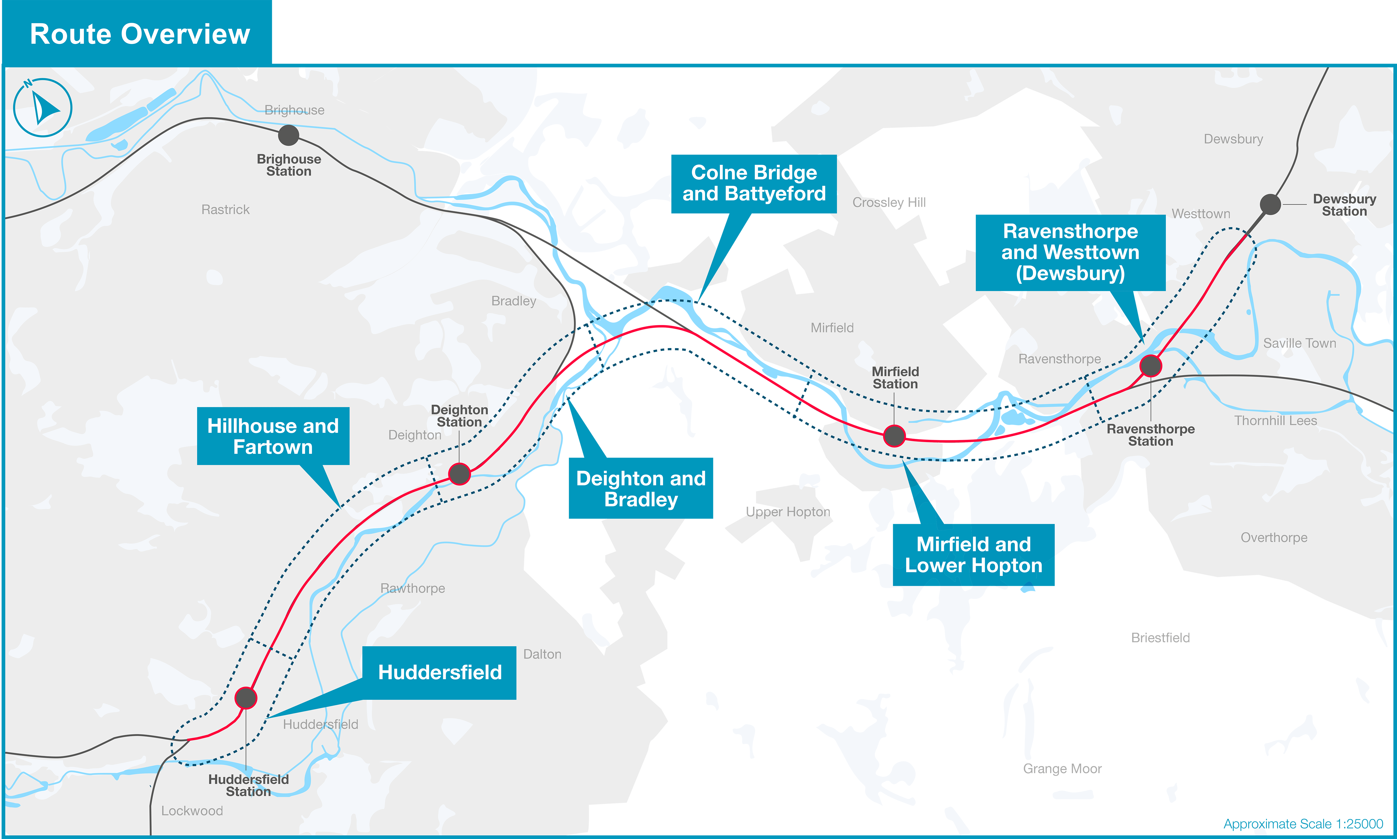
Yeah, I was initially surprised to learn that SFCs and AT are different ways of achieving similar things when in comes to enabling higher power. The big difference, however, being that SFCs suddenly open up a lot more possible locations for supply points enabling more strategic GSP locations. This was all discussed in this really good PWI video about Hambleton Junction, which, I was pleased learn, was specifically designed to one day feed the line to Hull - great to see integration of TRUP and ECML PSU. The video also includes this fun graph. The stepped line for classic is because of booster transformers. The dash line for SFCs is island mode, and the full line is the theoretical implementation of SFCs in parallel. It also seems suggested that the final GSP for the current TRUP between Manchester and York will be an SFC at Ravensthorpe (at the site of Thornhill power station)

1755807635759.png

== Doublepost prevention - post automatically merged: ==

As far as I know Autotransformer points are small enough for it to not be unusual for them to be installed on the line masts,
I don't think I've ever seen this for a UK autotransformer site (ATS)! They generally don't have a giant footprint or anything but the number of them you would need does add up fast. The smaller ATSs on HS1 are more regular in spacing than on XR or GWML, but those ones are also a lot bigger. I think this would be to do with the amount of current expected to be handled. For the heavily used electric railways you speak of, I wonder if that heavy use might prohibit ATSs from becoming fully structurally mounted
and I'm not even sure if they need to have any circuit breakers, although including a three pole circuit breaker to isolate a transformer fault is probably a good idea.
GWML pioneered a new protection scheme where ATSs are not fitted with circuit breakers at all and instead are programmed together with adjacent Feeder ("ATFS") and Midpoint substations ("MPATS"). When a fault is detected on an OLE circuit, the circuit breakers for all OLE+ATF circuits at the next ATFS and MPATS immediately open shutting down the whole line, then motorised isolator switches open up at the relevant ATSs to isolate the fault (I don't know how the system knows exactly where across the circuit the fault is), all the circuit breakers then reclose resuming normal feeding around a small bit of OLE that is isolated by those switches. The whole thing takes about 3 seconds so there's no consequences to the running of trains. It's known as "Rationalised Autotransformer System protection", or RATS protection and uses real-time IP based automatic communication between substations. Trading more complex protection programming/equipment for fewer circuit breakers.
Well that is the advantage I see here. We are going to have a lot of heavily used electric railways (supporting battery charging etc) as well as isolated charging islands. With auto transformer feeding we can plausibly feed detached segments of railway using a single phase railway feeder on a wood pole line in a way that wouldn't really be feasible otherwise.
I would quite like to see 25kV electrification take more of "distribution operator" type format in that way! In reality though, I think they would incorporate the well established practices of 750V DC and put all the HVAC distribution lines in underground cables.
 
Last edited:

Dazza12

Member
Joined
10 Aug 2022
Messages
18
Location
Derby
Hi,
Yeah, I was initially surprised to learn that SFCs and AT are different ways of achieving similar things when in comes to enabling higher power. The big difference, however, being that SFCs suddenly open up a lot more possible locations for supply points enabling more strategic GSP locations. This was all discussed in this really good PWI video about Hambleton Junction, which, I was pleased learn, was specifically designed to one day feed the line to Hull - great to see integration of TRUP and ECML PSU. The video also includes this fun graph. The stepped line for classic is because of booster transformers. The dash line for SFCs is island mode, and the full line is the theoretical implementation of SFCs in parallel. It also seems suggested that the final GSP for the current TRUP between Manchester and York will be an SFC at Ravensthorpe (at the site of Thornhill power station)

View attachment 186823
[...]
That graph just shows a whole slew of problems with the industry approach:
1. People are failing to understand that ATFS is a feature of the OLE whilst SFC is a type of feeding arrangement.
2. Those proposing SFCs appear to be completely unconcerned about the ongoing costs (which is where SFCs tend to lose over traditional feeding arrangements) - for example they aren't paying for all the energy lost implied by that voltage sag as the ORR will happily recover the cost for them through EC4T charges to the operators. Not very green!
3. No-one has thought about combining SFC and ATFS and seeing what the solution looks like.
4. The position of the line for ATFS (and some extent FS) has been chosen more or less at random whilst the huge voltage excursions (i.e. losses!) for SFC are necessary to make SFCs look competitive with AFTS in terms of number of feeders.

Straight transformer based and SFC based feeders each have pros and cons and the choice depends on circumstances. Similarly, plain OLE or ATFS OLE also have pros and cons.

You have to remember that SFC can be cheap from a capital cost perspective, that is great for funders but if we end up spending the money on ongoing costs instead then we haven't actually achieved a saving.
 
Joined
5 Aug 2015
Messages
896
Location
Norfolk
Hi,

That graph just shows a whole slew of problems with the industry approach:
1. People are failing to understand that ATFS is a feature of the OLE whilst SFC is a type of feeding arrangement.
Surely AT is also taxonomically a feeding arrangement? It provides a 50kV ring that is regularly connected to the contact wire to provide voltage support - in addition that 50kV ring runs 180degrees out of phase to the contact wire providing some EMI reduction. The way I see it, SFC is a feature of the feeder station but otherwise "classic" feeding. (Which these days is RCS only).
2. Those proposing SFCs appear to be completely unconcerned about the ongoing costs (which is where SFCs tend to lose over traditional feeding arrangements) - for example they aren't paying for all the energy lost implied by that voltage sag as the ORR will happily recover the cost for them through EC4T charges to the operators. Not very green!
Do you mean that the initial voltage has to set so high for SFC (so that it doesn't go under 19kV by the mid-point) that you end up wasting power?
3. No-one has thought about combining SFC and ATFS and seeing what the solution looks like.
Sounds like having 2 big expenses at once. But you do touch on a good point that SFCs are Siemens's thing, while AT has different companies behind it (ABB?) and as such Siemens does seem to pretend other options don't exist in their messaging. I think AT had it's time in the limelight in the ElectricSpine/CP5 era of works. Now that we know in clear terms what the price tags are, people are turned off from it. The very same thing could absolutely happen to SFCs since we don't yet know from a conclusion of a few projects what the cost ends up being.
4. The position of the line for ATFS (and some extent FS) has been chosen more or less at random whilst the huge voltage excursions (i.e. losses!) for SFC are necessary to make SFCs look competitive with AFTS in terms of number of feeders.
Yeah the whole impression of the actual lecture, however, was that they'd use SFC substations more regularly than ATFSs are placed because connections for an SFC FS should be a lot more available than for normal FS or ATFS.
 

hwl

Established Member
Joined
5 Feb 2012
Messages
8,252
Hi,

That graph just shows a whole slew of problems with the industry approach:
1. People are failing to understand that ATFS is a feature of the OLE whilst SFC is a type of feeding arrangement.
2. Those proposing SFCs appear to be completely unconcerned about the ongoing costs (which is where SFCs tend to lose over traditional feeding arrangements) - for example they aren't paying for all the energy lost implied by that voltage sag as the ORR will happily recover the cost for them through EC4T charges to the operators. Not very green!
3. No-one has thought about combining SFC and ATFS and seeing what the solution looks like.
4. The position of the line for ATFS (and some extent FS) has been chosen more or less at random whilst the huge voltage excursions (i.e. losses!) for SFC are necessary to make SFCs look competitive with AFTS in terms of number of feeders.

Straight transformer based and SFC based feeders each have pros and cons and the choice depends on circumstances. Similarly, plain OLE or ATFS OLE also have pros and cons.

You have to remember that SFC can be cheap from a capital cost perspective, that is great for funders but if we end up spending the money on ongoing costs instead then we haven't actually achieved a saving.
I pretty much agree.

3. I where I think things get interesting. Which happens to be the norm in 3rd and 4th rail land for decades (12 pulse rectifier starting off with 33kV/11kV with twin transformers in star and delta configurations to give two lower voltage 3phase output supplies with phase shift injected between them which mean not that much further clean up is needed) but balances input phase loadings.

The big down side for AT is that in the typical twin transformer installs two of the three phases are more loaded differently than the third. SFC is useful because it load spreads across all three phases in other countries it is used to dynamically balance any imbalances in phases making Nat Grid and DNOs happier which should bring down some for the phase imbalance charges (not mentioned).
SFC can also do active power factor correction (to be honest many modern 3 phase EMUs and locos do a good job here already). Hence SFC could be useful in the doing pre-emptive power factor correction (e.g. AFE) for the step down transformers used for either SFC or AT. The interesting question is what the ideal power factor for grid stability though a typical day - the answer is not 1...
Sounds like having 2 big expenses at once. But you do touch on a good point that SFCs are Siemens's thing, while AT has different companies behind it (ABB?) and as such Siemens does seem to pretend other options don't exist in their messaging. I think AT had it's time in the limelight in the ElectricSpine/CP5 era of works. Now that we know in clear terms what the price tags are, people are turned off from it. The very same thing could absolutely happen to SFCs since we don't yet know from a conclusion of a few projects what the cost ends up being.

Yeah the whole impression of the actual lecture, however, was that they'd use SFC substations more regularly than ATFSs are placed because connections for an SFC FS should be a lot more available than for normal FS or ATFS.

ABB's EHV Grid business was sold to Hitachi recently. (ABB are the leading vehicle fast charger equipment supplier globally as well as doing all the power electronics for the 68, 88, 92, 93 and 99)
ABB can do SFCs and undersea DC etc but ABB weren't aren't afraid to sell boring old school stuff if it is the right thing (unlike Siemens who love always trying to upsell the latest tech).


AT could be interesting if it align with future shape of the grid thinking e.g. it can help NatGrid and DNOs avoid some upgrades by taking loads in useful places.

It is going to be entertaining when there is lots of discovery that the "battery can do anything" fan club discovers that huge upgrades are needed for battery charging in the ideal locations from a simple rail only point of view.
 

HSTEd

Veteran Member
Joined
14 Jul 2011
Messages
20,297
2. Those proposing SFCs appear to be completely unconcerned about the ongoing costs (which is where SFCs tend to lose over traditional feeding arrangements) - for example they aren't paying for all the energy lost implied by that voltage sag as the ORR will happily recover the cost for them through EC4T charges to the operators. Not very green!
Since this is an AC system, we have to be a little careful about assuming that volt drop is synonymous with resistive losses.
Even if we ignore all other copper in the system, a 60km long contact wire only has a resistance of about 9 ohms.
With a nominal 4-5MVA load of ~200A, the resistive volt drop in the contact wire is 1800V, and in reality the catenary wire will cut that roughly in half. Thats if we assume no load sharing wtih adjacent lines.

The volt drop here is primarily inductive in nature, and whilst it reduces voltages at the train (thus increasing current draw and thus resistive losses), it does not drive energy losses directly.

Consequently, since an SFC can achieve higher voltages over much of the line (thanks to not having to account for the tendency of transformer secondary voltages to sag under load), an SFC may achieve lower losses than a conventional feeding arrangement in many situations.
 
Joined
28 Oct 2017
Messages
251
Since this is an AC system, we have to be a little careful about assuming that volt drop is synonymous with resistive losses.
Good point.

Consequently, since an SFC can achieve higher voltages over much of the line (thanks to not having to account for the tendency of transformer secondary voltages to sag under load), an SFC may achieve lower losses than a conventional feeding arrangement in many situations.
I have two responses to this. The first is surprise that there isn't a tap changer to regulate voltage in the conventional system (although these are both a capital and maintenance cost). The tap change relay can be configured to raise the local voltage set point as the current rises and so reduce the transformer voltage drop passed on.

The other is that I would expect the increased losses cost of the SFC to be mostly in the converter itself, not the conductors. The power supplied has to flow through the power semiconductors (roughly a rectifier and an inverter) plus the losses in whatever energy storage deals with the phase shifts (either inductor or capacitor). I suspect a second set of transformer losses because I find operating the semiconductors at 33/25kV unlikely - but I may be wrong about this, because HVDC links manage (I understand) without a lower voltage DC link.
 

HSTEd

Veteran Member
Joined
14 Jul 2011
Messages
20,297
I have two responses to this. The first is surprise that there isn't a tap changer to regulate voltage in the conventional system (although these are both a capital and maintenance cost). The tap change relay can be configured to raise the local voltage set point as the current rises and so reduce the transformer voltage drop passed on.
A tap changer works well for handling gradual changes in demand on the transformer.
But a rail feeder can go from several megawatts to zero instantaneously (train goes out of section).

I doubt a tap changer would be able to keep up with that without several seconds of far too high voltage on the line, which could damage things.
The other is that I would expect the increased losses cost of the SFC to be mostly in the converter itself, not the conductors. The power supplied has to flow through the power semiconductors (roughly a rectifier and an inverter) plus the losses in whatever energy storage deals with the phase shifts (either inductor or capacitor). I suspect a second set of transformer losses because I find operating the semiconductors at 33/25kV unlikely - but I may be wrong about this, because HVDC links manage (I understand) without a lower voltage DC link.
I believe he converters tend to drive the line directly, with transformers on the grid side. However I don't know the topology of any given converter.
 

Richard123

Member
Joined
11 Nov 2018
Messages
110
Location
Rugby
Good point.


I have two responses to this. The first is surprise that there isn't a tap changer to regulate voltage in the conventional system (although these are both a capital and maintenance cost). The tap change relay can be configured to raise the local voltage set point as the current rises and so reduce the transformer voltage drop passed on.

The other is that I would expect the increased losses cost of the SFC to be mostly in the converter itself, not the conductors. The power supplied has to flow through the power semiconductors (roughly a rectifier and an inverter) plus the losses in whatever energy storage deals with the phase shifts (either inductor or capacitor). I suspect a second set of transformer losses because I find operating the semiconductors at 33/25kV unlikely - but I may be wrong about this, because HVDC links manage (I understand) without a lower voltage DC link.
Indeed, tap changers have been tried on railway transformers and rapidly fail, as well as giving over/under-voltage as they can't chase the railway load as quickly as it varies.

I honestly can't understand what was being said upthread about the SFC "having higher losses in the OLE" and lines being arbitrarily placed?

Transformer supplies are also tapped as high as possible, but there is volt drop across it under load, it's just the reality of transformers - look at the voltage on the train as it passes the feeder station. That's why there is a difference. Lower voltages lead to higher losses (it's a current squared relationship). Literally the exact opposite of Dazza12's post?
 

HSTEd

Veteran Member
Joined
14 Jul 2011
Messages
20,297
A 50kV railway in the US (the now defunct Black Mesa and Lake Powell) had a series capacitor bank placed some distance from the substation to counteract the inductive effects of the contact line. The far section of wire was connected to the near section through the capacitor.

Has that been done anywhere else that anyone is aware of?
 
Joined
5 Aug 2015
Messages
896
Location
Norfolk
Bit of a change of subject (sorry) but I thought this was quite interesting.
I was poking around in the final report on the infamous inferno at North Hyde substation that took out Heathrow. And found this in the basic description of the site.
The majority of the circuits connecting to the North Hyde 66kV busbars site feed the distribution network and are owned by SSEN Distribution, with the rest of the circuits feeding either Network Rail or data centre demand and are owned by these parties
This refers to original grid connection for the heathrow express system (Hayes FS) - but I'm quite surprised to hear it was powered off 66kV! I was under the impression it was not considered possible to go lower than 132kV on a normal system.
 

Nottingham59

Established Member
Joined
10 Dec 2019
Messages
3,330
Location
Nottingham
It is going to be entertaining when there is lots of discovery that the "battery can do anything" fan club discovers that huge upgrades are needed for battery charging in the ideal locations from a simple rail only point of view.
That's not necessarily the case. Take Oxford as an example. AIUI there is an EMU stopper shuttling between Paddington and Didcot, and a diesel stopper between Didcot and Oxford. Replacing both with a BEMU through service will increase the total electrical energy used, certainly, but doesn't necessarily add to peak loads.

Firstly, the BEMU does not have to recharge the instant it hits the wires. It can be programmed to recharge at predermined locations between Didcot and London that have spare capacity, or programmed to dynamically detect times when the supply is not constrained, and recharge at those times when supply is available. Peak loads on the OHLE would not necessarily increase.

Secondly, with appropriately smart control systems, the BEMU could be programmed to switch back to battery mode when it is under the wires to relieve temporary overloads on the system. Such switching would actually increase the overall capacity of the existing OHLE, though the extra load would have to be made up again later of course.

And thirdly, if the battery were big enough, you could run on battery power through much of day, and recharge at night when the feeder stations will have plenty of spare capacity.

Batteries on trains can reduce peaks loads, and therefore costs of electrification. as well as increase them.
 

HSTEd

Veteran Member
Joined
14 Jul 2011
Messages
20,297
This refers to original grid connection for the heathrow express system (Hayes FS) - but I'm quite surprised to hear it was powered off 66kV! I was under the impression it was not considered possible to go lower than 132kV on a normal system.
This is normal wisdom, but as with all things there are many exceptions. Unusual site conditions will allow (or require) feeds to be taken in unusual ways

Especially considering the Heathrow Branch is unlikely to have particularly high power demand given the low speeds.
 

buz33

Member
Joined
21 Nov 2009
Messages
35
It also seems suggested that the final GSP for the current TRUP between Manchester and York will be an SFC at Ravensthorpe (at the site of Thornhill power station)
The planning documents submitted for the TWAO show the two SFCs as being located within the Ravensthorpe triangle on the opposite side of the railway from the power station.


NR13 Planning Drawing - Ravensthorpe Area - Key Plan (1).pdf
NR13 Planning Drawing - Ravensthorpe Triangle - Proposed Plan (4).pdf
 
Joined
5 Aug 2015
Messages
896
Location
Norfolk
The planning documents submitted for the TWAO show the two SFCs as being located within the Ravensthorpe triangle on the opposite side of the railway from the power station.


NR13 Planning Drawing - Ravensthorpe Area - Key Plan (1).pdf
NR13 Planning Drawing - Ravensthorpe Triangle - Proposed Plan (4).pdf
Thanks for those!
Do you have any info on what the feeding area of ravensthorpe will be? It could probably go all the way east to Copley Hill in Leeds throat. But there'll have to be a border somewhere westwards with Heyrod ATFS. I think Standedge Tunnel is the NwR region boundary, so it'd make some sense to put a midpoint near there so that ECR boundaries can nicely match maintenance regions. But normally that would be pretty low down on priorities.
 

ryan125hst

Established Member
Joined
2 Jun 2011
Messages
1,327
Location
Retford
View attachment 186812
In this diagram, the two lines at the bottom correspond to the "up" and "down" lines of two track plain-line. The big black rectangles are neutral sections and the diagonal lines (at each intermediate traction sectioning location (or "TSL")) are either insulated overlaps or section insulators (same function different kinds of OLE component). This is quite meaningfully different from an overhead line neutral section (aka OHNS).
So with this how would it be possible for the first feeder station to feed beyond the midpoint track section to its right?

I'd be interested to know why 25kV was picked in the first place. There might be something to be said for the size of insulators within internal components of a train. Especially for multiple units but I'm just guessing.
I've got down a bit of a rabbit hole over the last few days of looking at railways in Europe. I didn't realise how many different voltages are used: 1.5kV DC in France and the Netherlands, 3kV DC in Belgium and 15kV 16 2/3 Hz in Germany and Switzerland. It makes you wonder why all these different voltages were chosen, presumably due to technical limitations many decades ago. The odd German frequency is the most intriguing.

Speaking of which, HS1 and the Channel Tunnel must have a very good power capacity as each Class 374 set can draw up to 16MW of traction power. A couple of those accelerating and the power supply would know about it!
 

GRALISTAIR

Established Member
Joined
11 Apr 2012
Messages
10,492
Location
Preston Lancs
Speaking of which, HS1 and the Channel Tunnel must have a very good power capacity as each Class 374 set can draw up to 16MW of traction power. A couple of those accelerating and the power supply would know about it!
in fairness, without going too far OT, it really would have been the height of folly to spend all that money on tunneling and other infrastructure to then skimp on probably the lowest cost item - power!
 

Richard123

Member
Joined
11 Nov 2018
Messages
110
Location
Rugby
So with this how would it be possible for the first feeder station to feed beyond the midpoint track section to its right?


I've got down a bit of a rabbit hole over the last few days of looking at railways in Europe. I didn't realise how many different voltages are used: 1.5kV DC in France and the Netherlands, 3kV DC in Belgium and 15kV 16 2/3 Hz in Germany and Switzerland. It makes you wonder why all these different voltages were chosen, presumably due to technical limitations many decades ago. The odd German frequency is the most intriguing.

Speaking of which, HS1 and the Channel Tunnel must have a very good power capacity as each Class 374 set can draw up to 16MW of traction power. A couple of those accelerating and the power supply would know about it!
Not as much as you might think: the high speeds come with long distances between trains and it's only two tracks. Aggregate load of more lower power trains on conventional lines can be much harder to handle, particularly freight (which can draw maximum power for extended periods)...
 

D365

Veteran Member
Joined
29 Jun 2012
Messages
13,170
in fairness, without going too far OT, it really would have been the height of folly to spend all that money on tunneling and other infrastructure to then skimp on probably the lowest cost item - power!
Try telling that to East West Rail!

[yes I’m being facetious - compared to high speed rail, it’s chalk and cheese]
 
Status
Not open for further replies.

Top