Maybe some enterprising enthusiast will get a Raspberry Pi (or even a Pico) to do the digital bit with programming for whatever route wanted. Depending on the actual display power requirement, it might then be possible to power the whole thing with ISB power bank.The screen does have this attached, but I have found out that it’s an issue with the screens in built power supply and nothing to do with the irreplaceable electronics.
I’m powering the display with a 5V power supply as I don’t have 110V for the original supply.
The issue with the power supply was hindering me using the display as even though I wasn’t using the supply, the wires were still connected and I’m assuming something had broke and was drawing a ton of current meaning it gave the logic board issues.
To fix this I just cut the wires to the supply and that solved the issue and it worked!

-
Our new ticketing site is now live! Using either this or the original site (both powered by TrainSplit) helps support the running of the forum with every ticket purchase! Find out more and ask any questions/give us feedback in this thread!
You are using an out of date browser. It may not display this or other websites correctly.
You should upgrade or use an alternative browser.
You should upgrade or use an alternative browser.
Class 365 PBC Unit and PIS system
- Thread starter WMasterJedi
- Start date
- Status
- Not open for further replies.
Sponsor Post - registered members do not see these adverts; click here to register, or click here to log in
R
RailUK Forums

WMasterJedi
Member
Haha, you say this and I've actually done it!Maybe some enterprising enthusiast will get a Raspberry Pi (or even a Pico) to do the digital bit with programming for whatever route wanted. Depending on the actual display power requirement, it might then be possible to power the whole thing with ISB power bank.
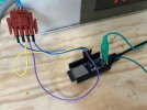
I have 3 internal screens from a 365, 2 raw metal enclosure ones and another (the one shown in the post you replied to). One of the raw metal screens is a master screen and is what I have in my full PIS setup while the other is a slave screen, instead of taking in FSK (Frequency Shift Keying) from the controller, it takes in direct clock and data signals for the shift registers and because of this I've been able to get it connected with an ESP32 and display custom stuff!
The direct clock and data signals actually go to the external connector of the display however they do go through some transistors this is because the shift registers use logic level 5V but the signal between the two screens is 12V (probably so then the signal doesn't fade over the distance in the train). This 12V works the exact same way with the exact same signals, just with a higher voltage. I have been able to use the screen just by connecting to the external connector however for now so then I don't need extra circuitry, I've just unplugged the internal connector between the LED/shift register board and the input board and connected the ESP32 output pins directly to the 5V inputs. Obviously this is temporary and eventually for a more permanent setup I'll just use the external connector with extra circuitry to up the ESP32's logic level voltage to 12V.
At the moment, I don't have any plans for the internal screen shown in the post you replied to.
-I'll also send some photos/videos of it in action later today.
Great, - looking forward to seeing them.Haha, you say this and I've actually done it!
I have 3 internal screens from a 365, 2 raw metal enclosure ones and another (the one shown in the post you replied to). One of the raw metal screens is a master screen and is what I have in my full PIS setup while the other is a slave screen, instead of taking in FSK (Frequency Shift Keying) from the controller, it takes in direct clock and data signals for the shift registers and because of this I've been able to get it connected with an ESP32 and display custom stuff!
The direct clock and data signals actually go to the external connector of the display however they do go through some transistors this is because the shift registers use logic level 5V but the signal between the two screens is 12V (probably so then the signal doesn't fade over the distance in the train). This 12V works the exact same way with the exact same signals, just with a higher voltage. I have been able to use the screen just by connecting to the external connector however for now so then I don't need extra circuitry, I've just unplugged the internal connector between the LED/shift register board and the input board and connected the ESP32 output pins directly to the 5V inputs. Obviously this is temporary and eventually for a more permanent setup I'll just use the external connector with extra circuitry to up the ESP32's logic level voltage to 12V.
At the moment, I don't have any plans for the internal screen shown in the post you replied to.
-I'll also send some photos/videos of it in action later today.
WMasterJedi
Member
Here it is! -Note: Images/Videos may look weird because of the camera's shutter speed.
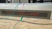
View attachment WhatsApp Video 2025-05-26 at 14.08.39_a73c2636.mp4
View attachment WhatsApp Video 2025-05-26 at 14.08.39_a73c2636.mp4
Well done, will you be attempting to emulate the route programming to give actual station calling info., and other in-service messages?Here it is! -Note: Images/Videos may look weird because of the camera's shutter speed.
View attachment 180751View attachment 180752
View attachment 180753
WMasterJedi
Member
I've copied every character that the screens can display from the test mode on the PIS system. The ESP32 is setup so that you just send it a string of characters and it will either display it statically or scroll it. (this is chosen with a special character at the start of the string that doesn't get shown)Well done, will you be attempting to emulate the route programming to give actual station calling info., and other in-service messages?
This means that I can make a program to run on my computer that when you select a custom made route, it will send the correct strings to emulate the real controller.
WMasterJedi
Member
In the past I’ve made a program that can play any northern line announcement just by entering its message number as it joins all the audio segments together automatically. Into this program I’ve implemented some code to send a message to the esp32 and this is the result:
(Obviously a northern line train is a little different to a 365 but they actually use the same dot matrix screens apart from the fact that the 365 screens are 12 16x16 segments and 1995 stock screens are 9 16x16 segments. However they were both made by JASMIN now KeTech.)
(Obviously a northern line train is a little different to a 365 but they actually use the same dot matrix screens apart from the fact that the 365 screens are 12 16x16 segments and 1995 stock screens are 9 16x16 segments. However they were both made by JASMIN now KeTech.)
WMasterJedi
Member
Cool little update!
I have designed and made this PCB to control one of the saloon displays!
It has two outputs one that’s 5V logic level and another which is 12V logic level.
The board also features an EEPROM as although the ESP32 can hold all of the character data in its memory, I’ve added this so then it can also work more like the original boards.
Note: I do plan to design a board with a FSK receiver (just like the one in the master saloon display) so then said board could work as a drop in replacement for the master saloon display board.
I have designed and made this PCB to control one of the saloon displays!
It has two outputs one that’s 5V logic level and another which is 12V logic level.
The board also features an EEPROM as although the ESP32 can hold all of the character data in its memory, I’ve added this so then it can also work more like the original boards.
Note: I do plan to design a board with a FSK receiver (just like the one in the master saloon display) so then said board could work as a drop in replacement for the master saloon display board.
Last edited:

Just arrived home and I’ve been able to get the speedometer panel working!
- I'd just like to ask how you managed to power the speedometer panel please? I actually also own one of these and haven't the foggiest of ideas currently!
Thanks!
WMasterJedi
Member
Hi Ben!
First of all these run on 110VDC which is something to keep in mind as it's quite high voltage.
Here is the wiring for the plug (If you look closely at the plug, with a torch is easier, each pin has a letter next to it)
If you have anymore questions revolving around the speedo panel, just ask! I'm quite experienced with these now as I own 2 of them!
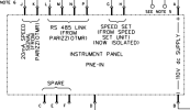
First of all these run on 110VDC which is something to keep in mind as it's quite high voltage.
Here is the wiring for the plug (If you look closely at the plug, with a torch is easier, each pin has a letter next to it)
If you have anymore questions revolving around the speedo panel, just ask! I'm quite experienced with these now as I own 2 of them!

D365
Veteran Member
- Joined
- 29 Jun 2012
- Messages
- 13,179
Once you’ve established the voltage of the speed signal, and whether the signal range is 0-20mA or 4-20mA, it will be possible to display a ’simulated’ speed.Hi Ben!
First of all these run on 110VDC which is something to keep in mind as it's quite high voltage.
Here is the wiring for the plug (If you look closely at the plug, with a torch is easier, each pin has a letter next to it)
If you have anymore questions revolving around the speedo panel, just ask! I'm quite experienced with these now as I own 2 of them!
View attachment 181836
WMasterJedi
Member
I have done this in two ways. (which both work)Once you’ve established the voltage of the speed signal, and whether the signal range is 0-20mA or 4-20mA, it will be possible to display a ’simulated’ speed.
Either with PWM or a 0-25ma module which can work with pretty much any microcontroller.
Last edited:

365 Networker
Member
- Joined
- 19 Jul 2019
- Messages
- 537
I wonder if the audio format for the announcement files could be .vqf ? I found some information on Wikipedia - https://en.wikipedia.org/wiki/TwinVQ
Of particular interest was this part:-
The proprietary version of TwinVQ can be also used for speech encoding. Compression technology specifically designed to handle voice compression was published by NTT. The NTT TwinVQ implementation supported sampling frequencies from 8 kHz or 11.025 kHz and bit rate from 8 kbit/s.
Of particular interest was this part:-
The proprietary version of TwinVQ can be also used for speech encoding. Compression technology specifically designed to handle voice compression was published by NTT. The NTT TwinVQ implementation supported sampling frequencies from 8 kHz or 11.025 kHz and bit rate from 8 kbit/s.

RacsoMoquette
Member
I have especially enjoyed hearing all the original announcements for the Class 365! Did the Networker Turbo Class 165 and 166 have a DVA? I know that they had a far less sophisticated internal display, it was LCD and static, it could only show a limited selection of characters each time. Did they have a DVA akin to the Class 365? Or was a DVA retrofitted in FGW days?
365 Networker
Member
- Joined
- 19 Jul 2019
- Messages
- 537
From old cab photos, I can see that the class 165 did have a similar keypad to the 365s:-I have especially enjoyed hearing all the original announcements for the Class 365! Did the Networker Turbo Class 165 and 166 have a DVA? I know that they had a far less sophisticated internal display, it was LCD and static, it could only show a limited selection of characters each time. Did they have a DVA akin to the Class 365? Or was a DVA retrofitted in FGW days?

I’ve never been able to find a video of any announcments pre FGW though. It may be that the facilities for announcements were there, but not used initially.
WMasterJedi
Member
That keypad does appear to be the same. - Not sure announcement wise though.From old cab photos, I can see that the class 165 did have a similar keypad to the 365s:-
View attachment 183688
I’ve never been able to find a video of any announcments pre FGW though. It may be that the facilities for announcements were there, but not used initially.
WMasterJedi
Member
This is the full PIS System as of currently.
I feel very happy with the current state of it, I've come a long way reverse engineering all of them and I've now finally got them into a permanent setup.
With all that being said posts in this thread will not stop, although posts about the PIS will (unless something really interesting happens or someone asks about it) posts from now on will be about my other 365 parts and making them into a cab sim to use with train sim classic!

I feel very happy with the current state of it, I've come a long way reverse engineering all of them and I've now finally got them into a permanent setup.
With all that being said posts in this thread will not stop, although posts about the PIS will (unless something really interesting happens or someone asks about it) posts from now on will be about my other 365 parts and making them into a cab sim to use with train sim classic!
simonmpoulton
Member
- Joined
- 25 Jun 2011
- Messages
- 217
Your PIS system looks great! Was wondering however if you had any luck in extracting and converting the audio from the EEPROMs? I'm currently toying with a data dump from a PCMCIA card which came from a Merseyrail system and am having the same kind of distorted output as in earlier from this thread!
Perhaps people can try to give better help with a copy of the dump!I'm currently toying with a data dump from a PCMCIA card which came from a Merseyrail system and am having the same kind of distorted output as in earlier from this thread!

simonmpoulton
Member
- Joined
- 25 Jun 2011
- Messages
- 217
The audio itself starts at byte offset 0x180000
Towards the end of the dump appears to be some kind of contents/lookup table for the audio, with the names of each file.
Ignore the duplicated characters and the top line seems to represent S (sound?) ann_502 (filename?). Further down you can see things like Ssta_bkc which is presumably Birkenhead Central.

simonmpoulton
Member
- Joined
- 25 Jun 2011
- Messages
- 217
Sounds a little bit clearer than what I managed. This is a real puzzle what format its recorded in, clearly not straight forward PCM that's for sure!Here's the best I've gotten so far with an hour or two of messing about.

bramling
Veteran Member
This is the full PIS System as of currently.
I feel very happy with the current state of it, I've come a long way reverse engineering all of them and I've now finally got them into a permanent setup.
With all that being said posts in this thread will not stop, although posts about the PIS will (unless something really interesting happens or someone asks about it) posts from now on will be about my other 365 parts and making them into a cab sim to use with train sim classic!
View attachment 185721
Really looks good! The massive amount of effort put into this has really paid off.
One question - would it be possible, please, to some time to make a recording of the full GN & SE announcements in the clear format seen in post 385? Having grown up with the 365s on GN it would be really great to finally hear these in their full glory.
One question - would it be possible, please, to some time to make a recording of the full GN & SE announcements in the clear format seen in post 385? Having grown up with the 365s on GN it would be really great to finally hear these in their full glory.
'This train is for bLondon Kings Cross, via Stevenage'

There was still a random 365 saying West Anglia Great Northern until the very end. Did a double take when I got on it and heard it.
WMasterJedi
Member
Unfortunately that is the one thing that has not been done, I have not been able to link the audio to the main PIS.Really looks good! The massive amount of effort put into this has really paid off.
One question - would it be possible, please, to some time to make a recording of the full GN & SE announcements in the clear format seen in post 385? Having grown up with the 365s on GN it would be really great to finally hear these in their full glory.
365 Networker
Member
- Joined
- 19 Jul 2019
- Messages
- 537
I might have said this before, but I'm fairly certain the PIS had two modes - one with announcements and one without. Finding how to change modes may be the issue. Another possibility I can think of of is that the visual controller and audio controller have different software versions installed - I assume you have tried both of the visual controllers? I'm also aware that the announcements were triggered by a wheel rotation counter - if this device is not connected, perhaps that may be causing the issue?Unfortunately that is the one thing that has not been done, I have not been able to link the audio to the main PIS.
WMasterJedi
Member
I've decided to start replicating some of the PCBs in PIS system and I've decided to start off with the master internal screen PCB!
It's not the best and before someone says, yes it does look very very messy, however to me it makes sense!
It's not finished either however I've done a pretty big chunk of it over the past 2 days!
 (Click the image for full quality)

It's not the best and before someone says, yes it does look very very messy, however to me it makes sense!
It's not finished either however I've done a pretty big chunk of it over the past 2 days!
(Click the image for full quality)
D365
Veteran Member
- Joined
- 29 Jun 2012
- Messages
- 13,179
Crikey. That’s a monumental challenge you’ve set yourself.
Does the intellectual property for the original ”Jasmin Electronics” PIS still exist somewhere?
Does the intellectual property for the original ”Jasmin Electronics” PIS still exist somewhere?
- Status
- Not open for further replies.