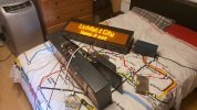
There are quite a few connectors on the back of the controller and they all connect to the PCB either using a serial connector or one of these connectors.
There are two of these connectors, one that is used for the input 110V signals to enable “Master” and this one which is just for the internal displays.
The pins are (labelled from left to right as shown in the image)
FSK TX, Ground, FSK RX, Unused and 110V out.
The 110V out is actually connected to the main power input of the internal displays, the big black relay as shown in the image gets switched on when the controller is in master and thus switches on 110V.
Before I found this out I was slightly confused on how people would of seen the “BRB class 465” message as it only appears when the screens first get power and only lasts for about 30 seconds however it now makes sense, because the screens only get power when the controller enters master which is when the cab gets setup (reverser out of off) that explains why people have seen the message as if you are in the train when the driver sets up the cab (reverser) you’ll be in there when the screens get power and show the message!