So in effect once the flywheel was removed the "booster set" simply became a standard dynamo / generator? Any booster function had goneThe booster sets were not removed on conversion as that is how the locos worked on both diesel and electric. The one-ton flywheels (used to provide more rotational energy to the mass of the motor and generator) were removed to save weight. To provide room for the Paxman engine, the booster set had to be moved longitudinaly in what was now an the engine room.
Unlike a Class 73 where the diesel and electric ends are seperate entities control wise (although parts of the electric main starting resistance grids are used during diesel transistion), the booster set on a Class 74 was either powered from the conductor rail or, at reduced power, from the diesel engine.

-
Our new ticketing site is now live! Using either this or the original site (both powered by TrainSplit) helps support the running of the forum with every ticket purchase! Find out more and ask any questions/give us feedback in this thread!
You are using an out of date browser. It may not display this or other websites correctly.
You should upgrade or use an alternative browser.
You should upgrade or use an alternative browser.
The mighty Class 74 (some questions!)
- Thread starter Harlequinuk
- Start date
Sponsor Post - registered members do not see these adverts; click here to register, or click here to log in
R
RailUK Forums

ac6000cw
Established Member
It wasn't called a 'booster' set because of the flywheel - it was because it could 'boost' (increase) or reduce the voltage to the traction motors relative to the 3rd rail voltage (or diesel generator output in a 74). This was more power efficient than using resistance control like on a 3rd rail EMU (especially in the lower power notches), and gave finer control of traction power.So in effect once the flywheel was removed the "booster set" simply became a standard dynamo / generator? Any booster function had gone
See https://en.wikipedia.org/wiki/British_Rail_Class_70_(electric)#Booster_control and https://en.wikipedia.org/wiki/Booster_(electric_power)#Reversible_booster for a more detailed explanation of how 'booster' control works.
There was enough stored energy in the rotating mass of the motor and generator parts of the machine (they are big old bits of kit) to still make it effective to get the loco over gaps in the conductor rail. As ac6000cw said earlier, the booster designation describes how the machine is controlled. It is simply a hefty old motor generator said that could be configured to either oppose (buck) or assist (boost) the conductor rail voltage.Surely though if you remove the flywheel then using the booster contravenes the law of conservation of energy? With nowhere to store energy there's nowhere to take it from when the extra voltage is required?
Even the small motor-generator sets on Southern Region EMU's took a while to run down to zero when the Auxiliary Isolating Switch was tripped. The motor-generator (booster) sets on Class 71's, with their flywheels, took ages to run down when tripped. They therefore had a booster brake to stop the motor-generator set more quickly. Can't remember if Class 74's did or not but I doubt it was a feature that was removed.
mike57
Established Member
The booster wasn't just about energy storage, To add to what @Tony73E wrote... (And correct me if I am wrong)With nowhere to store energy there's nowhere to take it from when the extra voltage is required?
The booster (thinking here the original SR CC1&2/class 70's) was a motor generator set (MG) which took the 650v supply from the 3rd rail and output an isolated variable voltage, roughly -ve650v to +ve650v with respect to the conductor rail voltage. (In reality I think it was more like 600v + and -)
This voltage was then connected in series with the conductor rail supply and applied to the traction motors. This means the traction motors are energised at a variable voltage from ~0v (-ve 600 in series with +ve650) to ~1200v, (+ve600 added to +ve650). Because the variable voltage is derived by modifying the field current and polarity of the generator in the MG set losses are reduced, as there is no longer a need for starting resistances. The traction motors are wound for 1200v DC. Because the MG set is only supplying half the rated voltage at the rated current the booster MG set only needs to be rated at half the installed horsepower of the traction motors.
The flywheel was then added to maintain power over gaps in the third rail. I have read reports that when motors were running at a low voltage (say 100v) for starting the gap could give a situation where instead of +100v on the traction motors you suddenly get 550v as you pass over the gap. I am not sure how this was managed in practice.
Its also worth remembering this system was developed by the Southern Railway well before any sort of power electronics were available for traction motor control, not even semiconductor diodes. A similar system was then carried forward into the 71's and 74's
The booster wasn't just about energy storage, To add to what @Tony73E wrote... (And correct me if I am wrong)
The booster (thinking here the original SR CC1&2/class 70's) was a motor generator set (MG) which took the 650v supply from the 3rd rail and output an isolated variable voltage, roughly -ve650v to +ve650v with respect to the conductor rail voltage. (In reality I think it was more like 600v + and -)
This voltage was then connected in series with the conductor rail supply and applied to the traction motors. This means the traction motors are energised at a variable voltage from ~0v (-ve 600 in series with +ve650) to ~1200v, (+ve600 added to +ve650). Because the variable voltage is derived by modifying the field current and polarity of the generator in the MG set losses are reduced, as there is no longer a need for starting resistances. The traction motors are wound for 1200v DC. Because the MG set is only supplying half the rated voltage at the rated current the booster MG set only needs to be rated at half the installed horsepower of the traction motors.
The flywheel was then added to maintain power over gaps in the third rail. I have read reports that when motors were running at a low voltage (say 100v) for starting the gap could give a situation where instead of +100v on the traction motors you suddenly get 550v as you pass over the gap. I am not sure how this was managed in practice.
Its also worth remembering this system was developed by the Southern Railway well before any sort of power electronics were available for traction motor control, not even semiconductor diodes. A similar system was then carried forward into the 71's and 74's
That is a good description of how boosters work - and that the flywheel is an add on to one.
When first read the booster / flywheel confusion, I could not be bothered to type out the explanation, especially after upthread had at one point succeded in confusing me before I realised what was actually being written.
Before the days of electronics there were a number of devices all based on rotating machines in combinations of AC and DC motor and generators on common shafts and / or wired together. A good example of this is the Ward Leonard set, another is the Metadyne. The Metadyne found use with LT in a few battery locos and one of the O/P/R type stock (I forget which one) although had no main line use. Ward Leonards to my knowledge found no GB traction application but were used by SNCF in 25 kV AC class CC14000 freight loco (but not the CC14100s). You could add a flywheel to any of the rotating shafts in those sets if certain characteristics were needed - but the flywheel is nonetheless only an add-on, not the set itself.
mike57
Established Member
A major application of Ward Leonard sets was lift control. We covered the theory when I was in college over 50 years ago.A good example of this is the Ward Leonard set.
Same here!A major application of Ward Leonard sets was lift control. We covered the theory when I was in college over 50 years ago.

Elecman
Established Member
Me tooSame here!
ac6000cw
Established Member
Picking up on 'rotating machines' used in traction applications, the US Norfolk and Western railroad LC-1 electric locos, dating from 1915, used a rotary phase converter to convert single-phase AC 750V (transformed down from 11kV 25Hz) to 3-phase 750V to drive 3-phase traction motors. The electrical equipment was from Westinghouse, with mechanical design and assembly by Baldwin. All were scrapped when the electrification was taken out of use in 1950 (when haulage reverted to steam power after boring a new summit tunnel and line relocations to reduce the ruling gradients from 2.5% to 1.4%).Before the days of electronics there were a number of devices all based on rotating machines in combinations of AC and DC motor and generators on common shafts and / or wired together. A good example of this is the Ward Leonard set, another is the Metadyne. The Metadyne found use with LT in a few battery locos and one of the O/P/R type stock (I forget which one) although had no main line use. Ward Leonards to my knowledge found no GB traction application but were used by SNCF in 25 kV AC class CC14000 freight loco (but not the CC14100s). You could add a flywheel to any of the rotating shafts in those sets if certain characteristics were needed - but the flywheel is nonetheless only an add-on, not the set itself.
A quote from https://en.wikipedia.org/wiki/Norfolk_and_Western_LC-1_Class :
The LC-1 were of the boxcab type and operated in a semi-permanent twin-unit configuration. The combined locomotive weighed 270–300 short tons (240–270 t) and was 105 feet 8 inches (32.21 m) long, making it both the largest and heaviest electric locomotive in the United States at the time of its introduction.[2]
The LC-1 collected power from overhead lines via pantograph; an on-board transformer stepped the overhead single-phase 11 kV AC down to 750 V. This in turn powered a rotary phase converter, which converted the single phase current to three phase 750 V. The use of three-phase aboard the LC-1 was recommended by Gibbs & Hill, a New York firm who consulted with N&W on the electrification project. According to William D. Middleton, Gibbs & Hill believed that the "ruggedness and simplicity, high output, uniform torque, and adaptability" of three-phase made it a superior choice to single-phase AC or DC for the mountainous Elkhorn area.[5]

In Hungary in 1932, the MÁV Class V40 locomotives used the Kandó rotary phase converter system to drive 3-phase traction motors, in this case starting from a 16kV 50Hz OHLE supply:

norbitonflyer
Established Member
O and P stock had Metadynes. (The difference between the two was in the position of the guards controls, P stock having it in the saloon, O stock in the rear cab, to suit different arrangements of the District and the Met). Converted to pneumatic camshaft control in the 1950s, and redesignated CO and CP.The Metadyne found use with LT in a few battery locos and one of the O/P/R type stock (I forget which one) although had no main line use.
The contemporary and visually similar Q38 stock had different control systems, to make them compatible with older G, K, L and M stock (renamed Q23, Q27, Q31 and Q35). Most Q38 cars were later converted to become R stock.
Harlequinuk
On Moderation
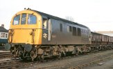
My next question! How far did the 74 work on freight?
Having found a fabulous photo or 2 when looking for coal wagons ; where did the 74 trundle around? Of course we know it was a challenge with anything out of Weymouth, but what about elsewhere on diesel?
Photo is the one i found on coal
Having found a fabulous photo or 2 when looking for coal wagons ; where did the 74 trundle around? Of course we know it was a challenge with anything out of Weymouth, but what about elsewhere on diesel?
Photo is the one i found on coal
Attachments

D6130
Established Member
Coal from Acton Yard to various South London distribution points.My next question! How far did the 74 work on freight?
Having found a fabulous photo or 2 when looking for coal wagons ; where did the 74 trundle around? Of course we know it was a challenge with anything out of Weymouth, but what about elsewhere on diesel?
Photo is the one i found on coal
Milk tankers from Acton Yard to Morden.
MoD traffic to and from West Moors....plus coal to Wimborne, on the same branch.
I heard an uncorroborated rumour that on one occasion one of them even reached Bedenham with an MoD trip on the Fareham-Gosport branch....although those trains were often quite long and heavy, so Eastleigh preferred to use a 33 when available.
I'm sure others will be able to think of more.

Sun Chariot
Established Member
You have read my mind! I was just about to ask if the former Gosport branch saw a 74.I heard an uncorroborated rumour that on one occasion one of them even reached Bedenham with an MoD trip on the Fareham-Gosport branch....although those trains were often quite long and heavy, so Eastleigh preferred to use a 33 when available.
Prompted by my wife and I driving across the old line on one of irs overbridges, this morning. The trackbed was converted into a dedicated bus-and-cycle route.
Salisbury & Dinton the latter military
Wimborne / West Moors (the latter fuel sump)
Blandford on milk
Ringwood demolition trains *** (obviously not regular)
I'm not saying they were regular on any of it but they did get there
I myself saw 6 different 74s at Salisbury; 2 at Ringwood
*** Actually after I typed that I'm not so sure they were demolition
Wimborne / West Moors (the latter fuel sump)
Blandford on milk
Ringwood demolition trains *** (obviously not regular)
I'm not saying they were regular on any of it but they did get there
I myself saw 6 different 74s at Salisbury; 2 at Ringwood
*** Actually after I typed that I'm not so sure they were demolition
Last edited:
Gloster
Veteran Member
Ringwood demolition trains *** (obviously not regular)
*** Actually after I typed that I'm not so sure they were demolition
West Moors-Ringwood closed, according to Hurst’s Register, on 7 August 1967. Were any 74 in service by then?
norbitonflyer
Established Member
According to Wikipedia the first was delivered to Stewarts Lane (travelling under its own power from Crewe Works) in November 1967West Moors-Ringwood closed, according to Hurst’s Register, on 7 August 1967. Were any 74 in service by then?
Merle Haggard
Established Member
Checking out when the first conversion entered service I've noticed something curious.
The SLS Journals stock changes lists seem to be based on official BR documents, but they show the locos concerned as only being 'renumbered'. For example, the first reference I can find, in the February 1968 Journal, is "Renumbered: E5006 to E6103 10/12/67".
The SLS Journals stock changes lists seem to be based on official BR documents, but they show the locos concerned as only being 'renumbered'. For example, the first reference I can find, in the February 1968 Journal, is "Renumbered: E5006 to E6103 10/12/67".
West Moors-Ringwood closed, according to Hurst’s Register, on 7 August 1967. Were any 74 in service by then?
What has closure date to do with 74 reaching Ringwood or not ?
I wrote demolition.
Demolition is AFTER closure - indeed a demolition train can only be that, and demolition does not start on Day +1 after closure (except in a few certain cases where some other works then goes on) and was usually months if not years later.
My memory tells me the tracks were still in place in Ringwood in 1969 or maybe even 1970. The old (very old) 38 bus route that I used to live on crossed the line at Ringwood station and a 74 seen from the bus on different days. This would have been more likely 1969 than 1968 or 1970 as the normal parental unit guided journeys took the 38 to Christchurch for either Mudeford or Hengistbury beaches, or onwards from Xchurch by trolleybus, the latter ceasing in 1969; as trolleybuses were travelled on a lot in their last year, to/from the Xchurch trolleybus turntable, I suggest 1969 the most likely.
So I am not confused that 74s - or at least one - reached Ringwood, only the year is elusive.
Maybe the failing is on my subsequent "not so sure about demolition" comment - given the closure dates, must have been demolition.
_
Evidence of 74 at Blandford, 1968 :

E6108 Blandford Forum
To see hundreds more photographs from the 1980’s, through to today, please go to my main website: table158photography.weebly.com/ The L.C.G.B. promoted railtour 'The Hampshireman' approaches its destination of Blandford Forum in Dorset on 3 November 1968 lead by Class 74 No.E6108 (TOPS number...
 www.flickr.com
Last edited:
Harlequinuk
On Moderation
Thank you all! Especially to that incredible photo of a 74 at Blandford Forum
So, with the travels stretching beyond the 3rd rail - how did they go to Crewe for heavy maintenance? A sedate journey on diesel?
Any photos?
So, with the travels stretching beyond the 3rd rail - how did they go to Crewe for heavy maintenance? A sedate journey on diesel?
Any photos?
D6130
Established Member
AFAIK, they never returned to Crewe....apart perhaps for some minor rectification works soon after conversion in 1967. Heavy maintenance was undertaken at Eastleigh - or occasionally Stewarts Lane depots....and major overhauls at Eastleigh Works.So, with the travels stretching beyond the 3rd rail - how did they go to Crewe for heavy maintenance? A sedate journey on diesel?

Helvellyn
Established Member
- Joined
- 28 Aug 2009
- Messages
- 2,570
On the flip side, as Class 71s they would have been hauled to Crewe for conversion to Class 74s. But did they work back to the Southern Region under their own power and/or undertake any test runs from Crewe?AFAIK, they never returned to Crewe....apart perhaps for some minor rectification works soon after conversion in 1967. Heavy maintenance was undertaken at Eastleigh - or occasionally Stewarts Lane depots....and major overhauls at Eastleigh Works.