Yesterday whilst talking about water columns, I decided to go back to the L&Y Society site to see what I could find out about two particular ones. I didn't find anything but looked on their Virtual Machine section and spotted a sub-section named Infrastructure - Perhaps I thought I might find some details in there...
What I did find were ten contract drawings for the branch line I'm researching and I thought you might like to know some things about them - In general terms I mean.
1. Pegs and Stakes - Each drawing for a particular structure such as a bridge is labelled as being at Peg x or Stake Y. This bares out what many of you have told me that the whole section of the branch was indeed marked out, they start at the western end (Blackburn) and of course start at 1, however the peg numbers differ from the stake numbers. That is you could be at peg 335 whereas in the same area the stake number might only be say 25. There also seems to be intermediate quarter stakes, e.g. 25.75.
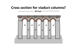
2. Abutments - These are a surprise! Not being an engineer, I simply thought these were just a solid rectangle of stone blocks. Wrong, the insides are link a mini viaduct in design. If you imagine all those intermediate columns connected at the top with arches, then you get the picture. Unlike a viaduct where the arches run the length of it, the abutment arches run width ways, parallel with say a road that the bridge will cross. The two for Simonstone station (carrying the line over a lane) have four columns inside (each 3 feet apart and 2 feet wide) connected by five arches. It makes me wonder now about Martholme viaduct, just how many columns the abutments there have inside...
3. Everything is measured in great detail even internal blocks of stones.
4, They are very specific as to what type of material is to be used and where.
5. Where possible there's standardisation - One sheet has an occupation over railway bridge, with the heading "Four of these", or farmer's occupation gates "30 of these as this one".
6. Occupation level crossings for pedestrians - For these, you had to turn to your left, open a side gate and go into one of those stretched out oval shapes (if that make sense), then you could close the gate and walk across the tracks. A similar gate system at the other side was also used.
7. Bridge names - Some names are obvious, if your going over a lane, usually you'd name it after that lane. When it comes to bridges in the middle on nowhere the L&Y liked to use the land owner's name or farmer's name. I first came across this about a year ago from engineer's line references - Shuttleworth's No. 1 and Shuttleworth's No. 2 named after Lord Kay-Shuttleworth. I hoped I'd find another example and one of these drawings shows a road over bridge - it's simply named Mr. Clark's. If I've got the location right, this is a bridge leading to a nearby farm. Presumably he's the farmer there, well maybe.
8. Drains - Most of the abutment walls have a drain pipe specified, the track bed shows troughs either side of the running lines too.
These undated drawings must have been made no later than the end of 1869, as invitations for tender were advertised January 1870. They also suggest that by then (1869) the route had been physically marked out by those pegs and stakes. I can see why someone who might be considering tendering for the contract to build a line might be wise to go and see the route for themselves before offering to fo it for a large amount of money - it's also common sense!
One other thing, one drawing shows permanent way diagrams - lengths of track 21 feet long, each section has 7 sleepers, which brings me onto something else I found - The contract for the unrelated Hoddlesden branch which ran to Darwen. This line was being built at the same time as the branch line I'm researching.
It gives agreed prices (per yard) of everything, but the real interesting thing to me is a section states that when X yards of embankment have been built, the contractor can then lay ballast and put down rails but only up to Y yards from where the current end of the embankment is.
This has implications for my on going research regarding "my old branch"...
If the L&Y state that under the right conditions you (the contractor) can start laying rails, it once again makes me wonder about the dates for the branch line rails. I can go back to 1876, they were there then, sadly a work man was run over and killed. Signal boxes were in place in 1875, there must have been track then? so possibly the very earliest some track could be extant, could be as far back as say 1871? a year after work was begun. On a side note - the drawings clearly show the lengths of rails as 21 feet, I read they were 27 feet initially?
Questions:
Are pegs really just shorter stakes?
These plans are drawings, partly in colour. What method of copying was available around 1870?
Surely as someone thinking of tendering, you want to take a copy of the plans and drawings home and study them rather than keep going back to the L&Y head office to look at them?
Have you seen drawing plans? if so, did anything surprise you about how something was built?
What I did find were ten contract drawings for the branch line I'm researching and I thought you might like to know some things about them - In general terms I mean.
1. Pegs and Stakes - Each drawing for a particular structure such as a bridge is labelled as being at Peg x or Stake Y. This bares out what many of you have told me that the whole section of the branch was indeed marked out, they start at the western end (Blackburn) and of course start at 1, however the peg numbers differ from the stake numbers. That is you could be at peg 335 whereas in the same area the stake number might only be say 25. There also seems to be intermediate quarter stakes, e.g. 25.75.
2. Abutments - These are a surprise! Not being an engineer, I simply thought these were just a solid rectangle of stone blocks. Wrong, the insides are link a mini viaduct in design. If you imagine all those intermediate columns connected at the top with arches, then you get the picture. Unlike a viaduct where the arches run the length of it, the abutment arches run width ways, parallel with say a road that the bridge will cross. The two for Simonstone station (carrying the line over a lane) have four columns inside (each 3 feet apart and 2 feet wide) connected by five arches. It makes me wonder now about Martholme viaduct, just how many columns the abutments there have inside...
3. Everything is measured in great detail even internal blocks of stones.
4, They are very specific as to what type of material is to be used and where.
5. Where possible there's standardisation - One sheet has an occupation over railway bridge, with the heading "Four of these", or farmer's occupation gates "30 of these as this one".
6. Occupation level crossings for pedestrians - For these, you had to turn to your left, open a side gate and go into one of those stretched out oval shapes (if that make sense), then you could close the gate and walk across the tracks. A similar gate system at the other side was also used.
7. Bridge names - Some names are obvious, if your going over a lane, usually you'd name it after that lane. When it comes to bridges in the middle on nowhere the L&Y liked to use the land owner's name or farmer's name. I first came across this about a year ago from engineer's line references - Shuttleworth's No. 1 and Shuttleworth's No. 2 named after Lord Kay-Shuttleworth. I hoped I'd find another example and one of these drawings shows a road over bridge - it's simply named Mr. Clark's. If I've got the location right, this is a bridge leading to a nearby farm. Presumably he's the farmer there, well maybe.
8. Drains - Most of the abutment walls have a drain pipe specified, the track bed shows troughs either side of the running lines too.
These undated drawings must have been made no later than the end of 1869, as invitations for tender were advertised January 1870. They also suggest that by then (1869) the route had been physically marked out by those pegs and stakes. I can see why someone who might be considering tendering for the contract to build a line might be wise to go and see the route for themselves before offering to fo it for a large amount of money - it's also common sense!
One other thing, one drawing shows permanent way diagrams - lengths of track 21 feet long, each section has 7 sleepers, which brings me onto something else I found - The contract for the unrelated Hoddlesden branch which ran to Darwen. This line was being built at the same time as the branch line I'm researching.
It gives agreed prices (per yard) of everything, but the real interesting thing to me is a section states that when X yards of embankment have been built, the contractor can then lay ballast and put down rails but only up to Y yards from where the current end of the embankment is.
This has implications for my on going research regarding "my old branch"...
If the L&Y state that under the right conditions you (the contractor) can start laying rails, it once again makes me wonder about the dates for the branch line rails. I can go back to 1876, they were there then, sadly a work man was run over and killed. Signal boxes were in place in 1875, there must have been track then? so possibly the very earliest some track could be extant, could be as far back as say 1871? a year after work was begun. On a side note - the drawings clearly show the lengths of rails as 21 feet, I read they were 27 feet initially?
Questions:
Are pegs really just shorter stakes?
These plans are drawings, partly in colour. What method of copying was available around 1870?
Surely as someone thinking of tendering, you want to take a copy of the plans and drawings home and study them rather than keep going back to the L&Y head office to look at them?
Have you seen drawing plans? if so, did anything surprise you about how something was built?