• Our new ticketing site is now live! Using either this or the original site (both powered by TrainSplit) helps support the running of the forum with every ticket purchase! Find out more and ask any questions/give us feedback in this thread!

Contract Drawings - Some General Observations

Status
Not open for further replies.

Andy873

Established Member
Joined
23 Mar 2017
Messages
1,421
Yesterday whilst talking about water columns, I decided to go back to the L&Y Society site to see what I could find out about two particular ones. I didn't find anything but looked on their Virtual Machine section and spotted a sub-section named Infrastructure - Perhaps I thought I might find some details in there...

What I did find were ten contract drawings for the branch line I'm researching and I thought you might like to know some things about them - In general terms I mean.

1. Pegs and Stakes - Each drawing for a particular structure such as a bridge is labelled as being at Peg x or Stake Y. This bares out what many of you have told me that the whole section of the branch was indeed marked out, they start at the western end (Blackburn) and of course start at 1, however the peg numbers differ from the stake numbers. That is you could be at peg 335 whereas in the same area the stake number might only be say 25. There also seems to be intermediate quarter stakes, e.g. 25.75.

2. Abutments - These are a surprise! Not being an engineer, I simply thought these were just a solid rectangle of stone blocks. Wrong, the insides are link a mini viaduct in design. If you imagine all those intermediate columns connected at the top with arches, then you get the picture. Unlike a viaduct where the arches run the length of it, the abutment arches run width ways, parallel with say a road that the bridge will cross. The two for Simonstone station (carrying the line over a lane) have four columns inside (each 3 feet apart and 2 feet wide) connected by five arches. It makes me wonder now about Martholme viaduct, just how many columns the abutments there have inside...

3. Everything is measured in great detail even internal blocks of stones.
4, They are very specific as to what type of material is to be used and where.

5. Where possible there's standardisation - One sheet has an occupation over railway bridge, with the heading "Four of these", or farmer's occupation gates "30 of these as this one".

6. Occupation level crossings for pedestrians - For these, you had to turn to your left, open a side gate and go into one of those stretched out oval shapes (if that make sense), then you could close the gate and walk across the tracks. A similar gate system at the other side was also used.

7. Bridge names - Some names are obvious, if your going over a lane, usually you'd name it after that lane. When it comes to bridges in the middle on nowhere the L&Y liked to use the land owner's name or farmer's name. I first came across this about a year ago from engineer's line references - Shuttleworth's No. 1 and Shuttleworth's No. 2 named after Lord Kay-Shuttleworth. I hoped I'd find another example and one of these drawings shows a road over bridge - it's simply named Mr. Clark's. If I've got the location right, this is a bridge leading to a nearby farm. Presumably he's the farmer there, well maybe.

8. Drains - Most of the abutment walls have a drain pipe specified, the track bed shows troughs either side of the running lines too.

These undated drawings must have been made no later than the end of 1869, as invitations for tender were advertised January 1870. They also suggest that by then (1869) the route had been physically marked out by those pegs and stakes. I can see why someone who might be considering tendering for the contract to build a line might be wise to go and see the route for themselves before offering to fo it for a large amount of money - it's also common sense!

One other thing, one drawing shows permanent way diagrams - lengths of track 21 feet long, each section has 7 sleepers, which brings me onto something else I found - The contract for the unrelated Hoddlesden branch which ran to Darwen. This line was being built at the same time as the branch line I'm researching.

It gives agreed prices (per yard) of everything, but the real interesting thing to me is a section states that when X yards of embankment have been built, the contractor can then lay ballast and put down rails but only up to Y yards from where the current end of the embankment is.

This has implications for my on going research regarding "my old branch"...

If the L&Y state that under the right conditions you (the contractor) can start laying rails, it once again makes me wonder about the dates for the branch line rails. I can go back to 1876, they were there then, sadly a work man was run over and killed. Signal boxes were in place in 1875, there must have been track then? so possibly the very earliest some track could be extant, could be as far back as say 1871? a year after work was begun. On a side note - the drawings clearly show the lengths of rails as 21 feet, I read they were 27 feet initially?

Questions:
Are pegs really just shorter stakes?
These plans are drawings, partly in colour. What method of copying was available around 1870?
Surely as someone thinking of tendering, you want to take a copy of the plans and drawings home and study them rather than keep going back to the L&Y head office to look at them?
Have you seen drawing plans? if so, did anything surprise you about how something was built?
 
Sponsor Post - registered members do not see these adverts; click here to register, or click here to log in
R

RailUK Forums

DelW

Established Member
Joined
15 Jan 2015
Messages
6,043
2. Abutments - These are a surprise! Not being an engineer, I simply thought these were just a solid rectangle of stone blocks. Wrong, the insides are link a mini viaduct in design. If you imagine all those intermediate columns connected at the top with arches, then you get the picture. Unlike a viaduct where the arches run the length of it, the abutment arches run width ways, parallel with say a road that the bridge will cross. The two for Simonstone station (carrying the line over a lane) have four columns inside (each 3 feet apart and 2 feet wide) connected by five arches. It makes me wonder now about Martholme viaduct, just how many columns the abutments there have inside...
Many apparently solid structures have large internal voids, to save materials and cost. For instance I've seen images of cathedral like spaces within the abutments of Clifton suspension bridge.
These plans are drawings, partly in colour. What method of copying was available around 1870?
Surely as someone thinking of tendering, you want to take a copy of the plans and drawings home and study them rather than keep going back to the L&Y head office to look at them?
Dyeline printing was widely used in engineering until replaced quite recently (early 2000s?) by large-size photocopiers (and AutoCAD!). The prints used to smell strongly of ammonia when first produced. Wikipedia has a section on early methods of printing drawings, though I think some of the terminology is American rather than British:
A blueprint is a reproduction of a technical drawing or engineering drawing using a contact print process on light-sensitive sheets introduced by Sir John Herschel in 1842.[1] The process allowed rapid and accurate production of an unlimited number of copies. It was widely used for over a century for the reproduction of specification drawings used in construction and industry. Blueprints were characterized by white lines on a blue background, a negative of the original. Color or shades of grey could not be reproduced.
 

Andy873

Established Member
Joined
23 Mar 2017
Messages
1,421
Dyeline printing was widely used in engineering until replaced quite recently (early 2000s?) by large-size photocopiers (and AutoCAD!). The prints used to smell strongly of ammonia when first produced. Wikipedia has a section on early methods of printing drawings, though I think some of the terminology is American rather than British:
Blueprinting! thanks, forgot that method would you believe.

Many apparently solid structures have large internal voids, to save materials and cost. For instance I've seen images of cathedral like spaces within the abutments of Clifton suspension bridge.
Based on the drawings showing the internal columns of abutments plus what you're saying I now even wonder about the external columns of the viaduct I've mentioned. Looks like they probably have internal columns too. The sandstone for the viaduct came from nearly four miles away, so using internal columns means less to transport, and that would have been an issue as the viaduct was begun even before the first shovel hit the ground.

Pegs - They seem to be spaced out at about 100 feet apart, but maybe they needed more denoting curves along the route?
 

DelW

Established Member
Joined
15 Jan 2015
Messages
6,043
Pegs - They seem to be spaced out at about 100 feet apart, but maybe they needed more denoting curves along the route?
From memory, when I was setting-out roads and motorways in the 1970s and early '80s, we set centre-line pegs at 20m intervals for off-setting fence lines and earthworks and drainage control, then at 10m intervals for carriageway construction and surfacing. The centre-line in each area wasn't just set once, it would have to be done multiple times during construction.

Obviously for railways the measurements would have been imperial and some of the works would have been different, but the principles would probably have been similar.
 

Rescars

Established Member
Joined
25 May 2021
Messages
2,585
Location
Surrey
Is/was there any correlation between the pegs and stakes used during construction and the distances measured in miles and chains after a line had opened?
 

TurboMan

Member
Joined
5 Apr 2022
Messages
422
Location
UK
The pegs could have been used for both line and level. It's a very old but easy technique to lay out groundworks using pegs set at the right height and position using boning rods. There's a good explanation of how boning rods are used here: https://www.pavingexpert.com/setout03

== Doublepost prevention - post automatically merged: ==

Is/was there any correlation between the pegs and stakes used during construction and the distances measured in miles and chains after a line had opened?
Very possibly, as the term chain comes from the use of a standard 22yd surveyor's chain (aka Gunter's chain) used for measuring and setting out. The length of the standard surveyor's chain explains why cricket pitches are 22yds long.
 

Andy873

Established Member
Joined
23 Mar 2017
Messages
1,421
From memory, when I was setting-out roads and motorways in the 1970s and early '80s, we set centre-line pegs at 20m intervals for off-setting fence lines and earthworks and drainage control, then at 10m intervals for carriageway construction and surfacing. The centre-line in each area wasn't just set once, it would have to be done multiple times during construction.

Obviously for railways the measurements would have been imperial and some of the works would have been different, but the principles would probably have been similar.
That's very interesting to know about how you went about marking roads etc.

Is/was there any correlation between the pegs and stakes used during construction and the distances measured in miles and chains after a line had opened?
As always @Rescars, you second guess my thoughts!

Very possibly, as the term chain comes from the use of a standard 22yd surveyor's chain (aka Gunter's chain) used for measuring and setting out. The length of the standard surveyor's chain explains why cricket pitches are 22yds long.

I can't find any correlation between the pegs / stakes and things like milepost etc.
I've tried, yards, chains, miles and even furlongs including fractions of them but nothing seems to fit these peg / stake sequence numbers.

Pegs and stakes - They now appear to me to be the same thing, just different wording.

Have a look at this map provided by the Nation Library of Scotland:


You will see four bridges relatively close together, all are over bridges and these are (starting from bottom left going east):

1. Mr. Clark's bridge. Contract drawing 9. At peg 43.
2. Road over to Lower Beet farm. Contract drawing 10. At stake 46.25
3. Tramway No. 1 Contract drawing 11. At peg 48.
4. Tramway No. 2 (but only named Tramway bridge). Contract drawing 12. At peg 59.

As you can see the contract drawing numbers are consecutive, after measuring there seems to be no correlation with measurement for mile posts, chains, yards, furlongs.

The only calculation that works are units of feet such as 50 and 100 (for peg / stake) sequence numbers. I'm wondering now if pegs / stakes were placed every 10 feet apart but only periodic ones were numbered? what does anyone think about that?

The only fly in the ointment is the second bridge in the above list, at peg 46.25.
Would that mean 2.5 feet beyond peg 46? That would work if all pegs are placed 10 feet apart?

Regarding that second bridge in the list - The one to Lower Beet farm... This bridge has a cast iron water pipe running at one side of it and at a height of 16 feet from the level of the rails. From the left side the pipe collects water from a stream which starts up on the hill, across the railway and then the pipe disappears downwards under the ground. I can only think this water is / was used as a feeder to the Leeds & Liverpool canal which is (at this point) parallel and close to the line. There is absolutely no other bridge on this section of line that has both a stream crossing it and being next to a road.

The first bridge on the list, Mr. Clark's - Now I've got my bearings right, this one which appears to go nowhere (on the left hand side) did run to some old coal pits, perhaps Mr. Clark owned them, who knows!

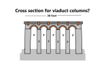
Viaduct column cross section:

If we adopt the principal that columns such as abutments have internal (hidden) columns then surely larger columns supporting a viaduct must follow that same principal?

Attached is what I nickname the 2,3,4,5,6 cross section of one of the nine supporting viaduct columns.

2. Because each internal column should be two feet wide based on all the other drawings.

3. Because the spacing between these internal columns is three feet.
4. Because there is room width wise to accommodate four internal columns.
5. They are connected by five arches at the top of the internal columns.
6. Still visible, six external protruding blocks which supported the temporary wooden arches on which the stone arches sat on during construction.

If we adapt this principal, then we cut down on cost, transportation of stone, and overall weight of the viaduct. It also gives us strength and stability, surely a corner stone of building something that needs to last. What do you engineers think?

The question still remains about the spacing and numbering of those pegs / stakes...
 

Attachments

  • Viaduct Cross Section.png
    Viaduct Cross Section.png
    36.5 KB · Views: 7

DelW

Established Member
Joined
15 Jan 2015
Messages
6,043
You will see four bridges relatively close together, all are over bridges and these are (starting from bottom left going east):

1. Mr. Clark's bridge. Contract drawing 9. At peg 43.
2. Road over to Lower Beet farm. Contract drawing 10. At stake 46.25
3. Tramway No. 1 Contract drawing 11. At peg 48.
4. Tramway No. 2 (but only named Tramway bridge). Contract drawing 12. At peg 59.

As you can see the contract drawing numbers are consecutive, after measuring there seems to be no correlation with measurement for mile posts, chains, yards, furlongs.

The only calculation that works are units of feet such as 50 and 100 (for peg / stake) sequence numbers. I'm wondering now if pegs / stakes were placed every 10 feet apart but only periodic ones were numbered? what does anyone think about that?

The only fly in the ointment is the second bridge in the above list, at peg 46.25.
Would that mean 2.5 feet beyond peg 46? That would work if all pegs are placed 10 feet apart?
I would be surprised if measurements along the line were in yards or feet. As per TurboMan's post, the standard measure was the chain (22yds or 66ft), divided into 100 links (each 7.92in). So I'd expect 46.25 to be 46 chains and 25 links i.e. 1017.5 yards from the origin point. Can that be fitted in to mean anything?

(Edited to add): the (physical) chain would almost certainly have been used to set the distance along the trace accurately. It would have been hooked to the last peg, pulled out to its full length, the next peg driven in there, and the process repeated. So the principal setting out pegs would more or less automatically be at one chain intervals.

Viaduct column cross section:

If we adopt the principal that columns such as abutments have internal (hidden) columns then surely larger columns supporting a viaduct must follow that same principal?

Attached is what I nickname the 2,3,4,5,6 cross section of one of the nine supporting viaduct columns.

2. Because each internal column should be two feet wide based on all the other drawings.

3. Because the spacing between these internal columns is three feet.
4. Because there is room width wise to accommodate four internal columns.
5. They are connected by five arches at the top of the internal columns.
6. Still visible, six external protruding blocks which supported the temporary wooden arches on which the stone arches sat on during construction.

If we adapt this principal, then we cut down on cost, transportation of stone, and overall weight of the viaduct. It also gives us strength and stability, surely a corner stone of building something that needs to last. What do you engineers think?
That looks quite a rational layout to me, though my masonry knowledge is limited! I know that a lot of the viaduct piers on e.g. the Settle and Carlisle route are hollow, though I don't think I've ever seen a drawing of the layout.
 
Last edited:

Rescars

Established Member
Joined
25 May 2021
Messages
2,585
Location
Surrey
If you want attractive hollow viaduct piers, how about the Ouse Valley viaduct on the Brighton main line?
 

John Webb

Established Member
Joined
5 Jun 2010
Messages
3,787
Location
St Albans
......These plans are drawings, partly in colour. What method of copying was available around 1870?.....
Others have already spoken of the copying method available - the colour was added by using water-colour paints applied by hand.
(At St Albans South we have on long-term loan the original track diagram from 1915. We are obliged to keep it covered by a heavy light-tight material, except when on display to visitors, to minimise fading of both the print and the water-colours.)
 

Andy873

Established Member
Joined
23 Mar 2017
Messages
1,421
Firstly, I must say thank you once more for all of your help - and it's a big help!

Very possibly, as the term chain comes from the use of a standard 22yd surveyor's chain (aka Gunter's chain) used for measuring and setting out. The length of the standard surveyor's chain explains why cricket pitches are 22yds long.
I would be surprised if measurements along the line were in yards or feet. As per TurboMan's post, the standard measure was the chain (22yds or 66ft), divided into 100 links (each 7.92in). So I'd expect 46.25 to be 46 chains and 25 links i.e. 1017.5 yards from the origin point. Can that be fitted in to mean anything?

(Edited to add): the (physical) chain would almost certainly have been used to set the distance along the trace accurately. It would have been hooked to the last peg, pulled out to its full length, the next peg driven in there, and the process repeated. So the principal setting out pegs would more or less automatically be at one chain intervals.
I fully accept what you're both saying, and that's the traditional way lines were measured, except it only worked once:

I decided rather than measure from the junction to one specific bridge, I measured backwards from the bridge towards the junction. It came out at the boundary of a field just before the junction. From this point to the junction there is nothing to cross at all, no streams, roads etc, so I thought so be it.

However, when I measure between bridges I know the peg / stake numbers of I'm still way off? and also, except for one, no peg / stake number has a point something after it. I would have expected more to say for example Peg X.10?

As said, I except what you're both telling me but I simply can't make it work, any ideas please?

Regarding my diagram of what I believe is inside each viaduct column - If I make the overall width 29 feet instead of 30 (any easy measuring mistake to make), then the two outer columns would be 3 feet each, which works perfectly with an overall width of 29 feet.

Going back to abutments:

I was looking at the drawings more closely this morning, and focused on the internal arches and why they are coloured pink / pale red - Bricks? turns out the answer is yes, they are made of bricks not stone.

These bricks are described as dry bricks - does that mean no mortar is to be used?

The radius of the arch for them is 1 foot, 6 inches, and the bricks (9 inch thick) are covered with asphalt, presumably that's for waterproofing?

Next up, drainage - The drawings state (in words) that each void between the internal columns has to have a 2 inch flag drain 6 inches x 2 inches, so I decided to go and look for evidence for these drains. I did a virtual trip under some of the old railway over bridges, most didn't show anything conclusive but two did. Green Lane (road under) bridge and Park Road bridge (both in Padiham). Here, I can see several rectangle holes at pavement level, given the spacing, I'm sure these are the drains running from inside the abutments.

Most bridges didn't show signs of the drains, but of course road and pavement levels can change over the years.

Would these drains also serve as a basic ventilation system?

Standardisation, I can only reiterate just how much of it there is.

Occupation level crossings - It seems I misread the diagrams with these. They all have one large gate (for your horse and cart to cross), and a side smaller gate for people to use. All the gates are to be made out of Oak, so they are not exactly cheap! On this section of the branch, the same main gate design is also used for farmer's fields, and it states thirty of these are needed. The side posts are 5' 6" high, but it doesn't say how wide they are, probably because they would have to be bespoke widths.

Tramway bridge - This one has a very steep gradient downhill, 1 in 6.88! Hope they used some sort of cable system to control the wagon's decent.

Tracks - One drawing shows various things including both Up and Down tracks at occupational level crossings. Strangely the distance between the two closest rails isn't given, however I was able to measure them as the drawings all have scales marked.

It turns out the gap is 4 feet, or possibly 4 feet, one inch. Does that sound like enough of a gap to allow trains to pass each other safely?
 
Last edited:

stuving

Member
Joined
26 Jan 2017
Messages
741
Maybe the numbers of the pegs aren't measurements at all. If these drawings are for contractors, they only need to know where to build relative to a reference point or points. I can imagine that the reference for bridge 23 was peg 23, and the line's chief surveyor would have put that in using a range of other information that the contractors didn't need. Other marks could be set off from that (possibly the stakes?) by junior surveyors. You do suggests that the marking out was done before the contractors were involved.
 

Rescars

Established Member
Joined
25 May 2021
Messages
2,585
Location
Surrey
I would be surprised if measurements along the line were in yards or feet. As per TurboMan's post, the standard measure was the chain (22yds or 66ft), divided into 100 links (each 7.92in). So I'd expect 46.25 to be 46 chains and 25 links i.e. 1017.5 yards from the origin point. Can that be fitted in to mean anything?

(Edited to add): the (physical) chain would almost certainly have been used to set the distance along the trace accurately. It would have been hooked to the last peg, pulled out to its full length, the next peg driven in there, and the process repeated. So the principal setting out pegs would more or less automatically be at one chain intervals.
Measurements in chains, subdivided into links seems to be the most likely explanation for something that, to modern eyes, looks like a decimal point. Is it possible that any of the measurement would have been made in rods (aka poles or perches). There are four rods to the chain, i.e. 5 1/2 yards or 1/320 of a mile. Does this help at all?

Another thought. Do you know how the branch was constructed? Were various parts of the construction let out to separate contactors perhaps? If so, might the pegs and stakes relate to internal measurements within the bounds of particular contracts, rather than the total length of the line?
Occupation level crossings - It seems I misread the diagrams with these. They all have one large gate (for your horse and cart to cross), and a side smaller gate for people to use. All the gates are to be made out of Oak, so they are not exactly cheap! On this section of the branch, the same main gate design is also used for farmer's fields, and it states thirty of these are needed. The side posts are 5' 6" high, but it doesn't say how wide they are, probably because they would have to be bespoke widths.

Tramway bridge - This one has a very steep gradient downhill, 1 in 6.88! Hope they used some sort of cable system to control the wagon's decent.

Oak gates would have been suitably strong and, not being prone to for, would presumably have needed little maintenance. Perhaps the sidepost dimensions were not stated because these would have been to standard dimensions in use elsewhere across the company's system.

1 in 6.88. A mineral tramway perhaps? Looks like a case for cable haulage in both directions!
 

DelW

Established Member
Joined
15 Jan 2015
Messages
6,043
Maybe the numbers of the pegs aren't measurements at all. If these drawings are for contractors, they only need to know where to build relative to a reference point or points. I can imagine that the reference for bridge 23 was peg 23, and the line's chief surveyor would have put that in using a range of other information that the contractors didn't need. Other marks could be set off from that (possibly the stakes?) by junior surveyors. You do suggests that the marking out was done before the contractors were involved.
I was wondering whether they might just be sequentially numbered reference points unrelated to distance, too. I'm sure that the tenderers would walk the route at least once, and numbered pegs might be sufficient for identifying each location. But (per post 1) the numbers go up surprisingly high if that's the case.
These bricks are described as dry bricks - does that mean no mortar is to be used?
I don't think I've ever seen that done. Dry-stone walls work because of the variety of shapes which can interlock, but that doesn't really work for bricks. Maybe the expectation was that bricks would be made on site from locally dug clay, and would need to be dried before use?
Next up, drainage - The drawings state (in words) that each void between the internal columns has to have a 2 inch flag drain 6 inches x 2 inches, so I decided to go and look for evidence for these drains. I did a virtual trip under some of the old railway over bridges, most didn't show anything conclusive but two did. Green Lane (road under) bridge and Park Road bridge (both in Padiham). Here, I can see several rectangle holes at pavement level, given the spacing, I'm sure these are the drains running from inside the abutments.

Most bridges didn't show signs of the drains, but of course road and pavement levels can change over the years.

Would these drains also serve as a basic ventilation system?
I have built bridges with voids in the concrete deck to reduce weight, and they always had a drain to each void. I'm not sure whether ventilation would be required, but the drain would provide it anyway.
Tracks - One drawing shows various things including both Up and Down tracks at occupational level crossings. Strangely the distance between the two closest rails isn't given, however I was able to measure them as the drawings all have scales marked.

It turns out the gap is 4 feet, or possibly 4 feet, one inch. Does that sound like enough of a gap to allow trains to pass each other safely?
That sounds very narrow. I don't know the exact normal value(s), but since the gap between up and down lines is often referred to as the "six foot", presumably it's somewhere around that.
 

Andy873

Established Member
Joined
23 Mar 2017
Messages
1,421
That looks quite a rational layout to me, though my masonry knowledge is limited! I know that a lot of the viaduct piers on e.g. the Settle and Carlisle route are hollow, though I don't think I've ever seen a drawing of the layout.

Maybe the numbers of the pegs aren't measurements at all. If these drawings are for contractors, they only need to know where to build relative to a reference point or points. I can imagine that the reference for bridge 23 was peg 23, and the line's chief surveyor would have put that in using a range of other information that the contractors didn't need. Other marks could be set off from that (possibly the stakes?) by junior surveyors. You do suggests that the marking out was done before the contractors were involved.

Measurements in chains, subdivided into links seems to be the most likely explanation for something that, to modern eyes, looks like a decimal point. Is it possible that any of the measurement would have been made in rods (aka poles or perches). There are four rods to the chain, i.e. 5 1/2 yards or 1/320 of a mile. Does this help at all?

Another thought. Do you know how the branch was constructed? Were various parts of the construction let out to separate contactors perhaps? If so, might the pegs and stakes relate to internal measurements within the bounds of particular contracts, rather than the total length of the line?
Until this morning I hadn't looked too closely at drawings 31 & 32.

No. 31 makes me even more curious - It's labelled as being at peg 352.20.
No. 32 has no peg number, it doesn't need one as this is the final bridge for the contractor, and it's the turnpike road just outside Padiham.

From the junction at the Blackburn end to this turnpike road is 6 miles, 60 chains.
No. 31 is only 570 feet from No. 32. If the peg numbers were to relate the distance from the junction, then No. 31's peg number should be between 480 and 540, which it clearly isn't.

Could (for measuring / construction purposes) this section of the branch have been sub divided into two or more sections? If so, the end of one sub section is the starting point of the next one? but that would mean resetting the peg numbers and that would cause confusion?

I'm absolutely sure chains and pegs were the method of measuring, but quite literally they don't add up!
 

stuving

Member
Joined
26 Jan 2017
Messages
741
That set of drawings does not include either an overall plan - mapping the route - or a set of general specifications of methods and materials. That renders any discussion of the placing of reference marks and the meaning of notes and instructions on the drawings difficult, and largely guesswork. However, the same L&Y Society Virtual Museum category does have 1874_Specifications_For_ Construction _Of_ Hoddlesden_Branch and 1883_Contracts_For_Works_At_Birkdale _And_Pendleton, which do cover methods and materials. While both are a few years later, the differences will not be great (but may be unknown).

In the drawings, not only is is masonry to be capped with asphalte, but the back of retaining walls is separated from the embankment material by "dry lining". My first thought was that this was to prevent the masonry being too wet, and probably linked to the use of lime mortar. I imagine that permanently wet masonry (and brickwork in particular) would call for "waterproof" or hydraulic mortar.

In the 1874 specifications only lime mortar is called for, "made from Halkin* Mountain limestone, fresh burnt, and made only as required, of one-third lime and two thirds sharp clean sand, measured dry, and mixed under rollers in a mill, with a proper proportion of water to make it of the required tenacity". But also "Roman cement or lias lime, if required by the engineer, in this contract, shall be of the best quality; all to be mixed fresh, as required for use". I take it that would be hydraulic (i.e. would set under water), due to its pozzolanic content.

The 1883 specifications include Portland Cement in both mortar and concrete, but also lime mortar and lime concrete. "All cement used in this contract shall be Portland of the best quality, weighing not less than 115 lbs. per Imperial striked bushel..." Lime concrete was to be made with hydraulic lime in lieu of cement. "The mortar for all foundation work must be made from Barrow (Leicestershire) hydraulic lime".

This neatly encapsulates how materials and practices evolved, and pretty rapidly, as Portland cement moved from being used just for sewers, piers, etc where it was most valuable, to becoming a common material for most building work.

I also measured the six foot on a drawing of a level crossing (no 34), and found it to be six feet pretty exactly. That was between outer rail faces, between gauge faces it would be about 6'5".

*I see that the Halkyn Mountain quarries did produce a small amount of hydraulic limestone, but as it's not mentioned in the specifications I guess that's not intended here. But if anyone knows better ...
 

Andy873

Established Member
Joined
23 Mar 2017
Messages
1,421
That set of drawings does not include either an overall plan - mapping the route - or a set of general specifications of methods and materials. That renders any discussion of the placing of reference marks and the meaning of notes and instructions on the drawings difficult, and largely guesswork.
I absolutely agree with you, for now, and for me, that's what it is, pure guesswork.

The 1883 specifications include Portland Cement in both mortar and concrete, but also lime mortar and lime concrete. "All cement used in this contract shall be Portland of the best quality, weighing not less than 115 lbs. per Imperial striked bushel..." Lime concrete was to be made with hydraulic lime in lieu of cement. "The mortar for all foundation work must be made from Barrow (Leicestershire) hydraulic lime".
And so on, the railway expected nothing less than high quality materials to be used, and the same goes for the workmanship.

The Hoddlesden contract:

I've spent the morning reading through the above contract, and quite frankly I (as a potential contractor) might have turned pale upon reading it!

There's so many catches, deadline in there, and if Sturges Meek (The chief L&Y engineer) isn't happy you don't get paid. The process of being paid goes something like this... At the end of every month, if Meek is happy with your progress you get a certificate and paid an agreed amount. However, the L&Y hold a percentage of that back. At the end of the year (perhaps December), if again that month's work is satisfactory, you get that payment plus half of the money held by the L&Y for that year, and so on.

Once the whole line is complete, and Mr. Meek agrees, you get the final payment including any money they held back (minus the interest of course!).

With such a contract and the process of construction, you can see how the L&Y keep the pressure up on the contractor.

The detailed costing (per cubic yard) is very specific. I must add the point that for any figure quoted in the 1870 - 1877 period, you have to add two zeros on to get an idea of the cost today. For example, £1 is now £100.

It also states that when you (the contractor) have completed 500 yards of trackbed through cuttings / embankments, you can lay ballast and rails. But they must not be laid to within 100 yards of the ends of either cuttings or embankments, and you are only allowed to use them for transporting soil etc.

I'm sure the L&Y would have a template contract which would be used and amended for each project?, on that basis the North Lancs Loop line would be very similar, and given the dates, similar prices per yard.

The other thing to note - a 12 month guarantee! That's what you the contractor has to give for your work after the whole project is complete.

All very interesting stuff!

Mr. Meek (after the board of the L&Y) had total control, upon his say so, you got paid or you didn't. the North Lancs loop wous built in two sections for reasons I won't go into again. Mr. Stone did the 6.75 mile section (Blackburn - outside Padiham), Mr. Gregson, the 2 miles 21 chains section (Padiham - Rose Grove (Burnley).

Gregson got into financial difficulties in 1874, Mr. Stone, for his persistence under difficult circumstances got the contract to build all three stations.

As for those peg numbers and distances, the only way I can make them work is to split Mr. Stone's section up into two, Blackburn - Great Harwood, then Great Harwood - Padiham, and that works, but who really knows?

Anyone interested in just how railway were built, bridges designed etc, I would suggest you spend some time looking at these engineer's drawings, contracts etc, if you like that kind of thing, you'll find them interesting to say the least.
 

Morayshire

Member
Joined
6 Feb 2019
Messages
303
There's so many catches, deadline in there, and if Sturges Meek (The chief L&Y engineer) isn't happy you don't get paid. The process of being paid goes something like this... At the end of every month, if Meek is happy with your progress you get a certificate and paid an agreed amount. However, the L&Y hold a percentage of that back. At the end of the year (perhaps December), if again that month's work is satisfactory, you get that payment plus half of the money held by the L&Y for that year, and so on.

Once the whole line is complete, and Mr. Meek agrees, you get the final payment including any money they held back (minus the interest of course!).

Sounds like a standard construction contract then using sometjing similiar to what was called the ICE Conditions of Contract (now called something else).

ICE = Institute of Civil Engineers by the way.

Process of keeping part of the payment back is called retention. Idea is to ensure that there is money to fix any defects upon completion of the defects period amongst other things.

With such a contract and the process of construction, you can see how the L&Y keep the pressure up on the contractor.

Goes both ways. There will be ways by which the contractor can put pressure on the client, in this case the L&Y. It is a very adversarial form of contract.

I'm sure the L&Y would have a template contract which would be used and amended for each project?, on that basis the North Lancs Loop line would be very similar, and given the dates, similar prices per yard.

Probably. Certainly in later years the ICE Conditions of Contract provided a standard set of Terms and Conditions plus there is a Civil Engineering Standard Method of Measurement which defines how you quantify the work to be done. Naturally there will be a lot of "adjustments" to clauses etc which means more money for the lawyers.

The other thing to note - a 12 month guarantee! That's what you the contractor has to give for your work after the whole project is complete.
12 months defect correction period is still standard in construction but it can be longer as well. Or shorter.

Once the 12 months is up, the retention is released and that should be that.

Aye, that'll be right...

Unless there is a defect which the contractor doesn't agree is a defect or doesn't want to fix in which case part of or all of the retention is used to pay the bill. Cue lots of arguments.
 

Ducatist4

On Moderation
Joined
29 Apr 2019
Messages
988
Location
Mansfield
These days half the retention (usually 2.5%) is released on practical completion and the other half is released at the end of the defects liability period (usually 12 months). Both the % and the period can be varied before the contract is signed though.
 
Joined
5 Jun 2022
Messages
34
Location
Hamilton, New Zealand
Sounds like a standard construction contract then using sometjing similiar to what was called the ICE Conditions of Contract (now called something else).

ICE = Institute of Civil Engineers by the way.

Process of keeping part of the payment back is called retention. Idea is to ensure that there is money to fix any defects upon completion of the defects period amongst other things.


Goes both ways. There will be ways by which the contractor can put pressure on the client, in this case the L&Y. It is a very adversarial form of contract.


Probably. Certainly in later years the ICE Conditions of Contract provided a standard set of Terms and Conditions plus there is a Civil Engineering Standard Method of Measurement which defines how you quantify the work to be done. Naturally there will be a lot of "adjustments" to clauses etc which means more money for the lawyers.


12 months defect correction period is still standard in construction but it can be longer as well. Or shorter.

Once the 12 months is up, the retention is released and that should be that.

Aye, that'll be right...

Unless there is a defect which the contractor doesn't agree is a defect or doesn't want to fix in which case part of or all of the retention is used to pay the bill. Cue lots of arguments.
I believe railway companies and engineers in those days were not exactly scrupulous in their dealings with contractors. There were a couple of court cases in the 1800s including one called McIntosh v Great Western Railway where a certain IK Brunel and the GWR were in frequent and flagrant breach of contracts. Somewhat reminiscent of Dickens’ “Jarndyce” case, the dispute took 19 years to reach a conclusion. The court drew a distinction between the Engineer‘s administrative and certification functions, and began to impose duties of fairness and impartiality when certifying work.

I am not familiar with current English construction contract law but I believe there are similar provisions to here in NZ and also in Australia where those duties of fairness and impartiality together with the Construction Contracts Act and the adjudication process would certainly have clipped Mr Meek’s wings had he tried those tactics today.
 

Rescars

Established Member
Joined
25 May 2021
Messages
2,585
Location
Surrey
I believe railway companies and engineers in those days were not exactly scrupulous in their dealings with contractors. There were a couple of court cases in the 1800s including one called McIntosh v Great Western Railway where a certain IK Brunel and the GWR were in frequent and flagrant breach of contracts. Somewhat reminiscent of Dickens’ “Jarndyce” case, the dispute took 19 years to reach a conclusion. The court drew a distinction between the Engineer‘s administrative and certification functions, and began to impose duties of fairness and impartiality when certifying work.

I am not familiar with current English construction contract law but I believe there are similar provisions to here in NZ and also in Australia where those duties of fairness and impartiality together with the Construction Contracts Act and the adjudication process would certainly have clipped Mr Meek’s wings had he tried those tactics today.
Enforcing contracts in the Victorian era could take a more robust form than is commonplace today. As an example, IKB vs Marchant and the Battle of Mickleton Tunnel!
 

Andy873

Established Member
Joined
23 Mar 2017
Messages
1,421
@Morayshire and @Ducatist4, Thanks both of you for your input on this, as a non engineer it's extremely helpful.

Enforcing contracts in the Victorian era could take a more robust form than is commonplace today. As an example, IKB vs Marchant and the Battle of Mickleton Tunnel!

I am not familiar with current English construction contract law but I believe there are similar provisions to here in NZ and also in Australia where those duties of fairness and impartiality together with the Construction Contracts Act and the adjudication process would certainly have clipped Mr Meek’s wings had he tried those tactics today.
Interesting, I guess some would push until they were told to stop one way or another.

Regarding the drawings:

As said, I'm not an engineer but I did do Engineering Drawing all those years ago at school, so for me, the drawings are quite easy to understand. For each structure say bridge, you have at least three drawings showing different angles.

They are Elevation - As if you were stood on the tracks looking at the over bridge.
Plan - As if you were directly over the bridge looking down from the sky.
Cross section - As if you've sliced through the bridge showing its internal features.

Regarding the Hoddlesden branch spec:

It really does look like a standard list of T&C's, Do's and Don'ts etc which is adapted to this specific project. If I'm right about that, then this document is like the Rosetta stone regarding my research.

Permanent way details:
This document is very revealing, in this case permanent way materials (rails, chairs, fishplates, sleepers etc) are provided by the railway company. When appropriate (engineer's say so), some of these are delivered to the nearest station, in this specific case it's Darwen station.

Once they have arrived there, the contractor has only a short time to collect them and take them away, otherwise he has to pay X pounds per day.

As soon as the contractor has hold of them he is responsible for them, including storage in a safe, secure, and dry location. These must be guarded, any loss or damage to them must be replaced at the contractor's own expense.

Laying of rails:
This seems to happen much sooner than I had imagined, on the say so of the resident engineer and provided sufficient work has been completed, the track can be placed on the trackbed. This must be no less than 500 yards, and must also be 100 yards away from any current work, no closer. The contractor is then allowed to use the rails.

From my point of view, as said, this makes the earliest track formation probably around 1871 (work began April 1870).

There was a fatal accident of 1876, one of the workers jumped onto the first mineral wagon, unfortunately he slipped and fell between the rails. The first two wagons passed him with no injuries, however whilst trying to escape the third one caused very severe injuries, and the poor chap died later.

Now this sad incident must be describing standard gauge wagons and track, if it was narrow gauge then I can't see how he wouldn't have been injured be even the first wagon. The point to this is I've always believed the track and wagons were standard gauge and not narrow gauge, the Haddelsden contract proves it.

Questions:

As there is no mention of the L&Y providing wagons to move the spoil along the tracks, does it mean the contractor has to provide his own wagons?

Did mineral wagons have intermediate brake settings, e.g. Half on / off etc?

You (the contractor) have to keep the tracks, sleepers etc, safe, secure and dry, would that imply some sort of a large wooden shed or something? My particular branch's construction start site is in the middle of the countryside and I don't think there would have been anything suitable in the nearby town.
 
Status
Not open for further replies.

Top