• Our new ticketing site is now live! Using either this or the original site (both powered by TrainSplit) helps support the running of the forum with every ticket purchase! Find out more and ask any questions/give us feedback in this thread!

Workington derailment 12/04/2023

Status
Not open for further replies.
Sponsor Post - registered members do not see these adverts; click here to register, or click here to log in
R

RailUK Forums

fadster

Member
Joined
28 Aug 2014
Messages
34
Wasn't there another one at, or near, Corby. If I remember rightly it resulted in fatalities.
31150 hit a runaway brake van and coal wagons near Corby tunnel in September 1975.
There was 1 fatality.
Paul.
 

Signal Head

Member
Joined
26 May 2013
Messages
460
You are awarded 10 points for correctly describing the operation of the 'snodget'! They come in two forms, insulated and non-insulated. The non-insulated type is just a means of attaching a track circuit bond cable to the rail, forming part of the track circuit itself so if broken off it simply causes a discontinuity in that TC. An insulated type contains a separate circuit, independant of the track circuit, or carrying the opposite polarity of the same circuit. In either case the device needs replacing once broken by a run-through before normal operations can resume.
Insulated interrupters have been the norm for new work for many years, even when wired into the TC itself. A problem with non-insulated ones is the possibility that the 'knock off' portion could fall against the rail and remake the circuit.

An insulated one (and cast iron portion of both variants is identical) is wired into the TC with the opposite polarity to the rail on which it is mounted, so even if it touches 'its' rail after breakage, it can't irregularly allow the TC to go clear.
 

MarkyT

Established Member
Joined
20 May 2012
Messages
7,567
Location
Torbay
Insulated interrupters have been the norm for new work for many years, even when wired into the TC itself. A problem with non-insulated ones is the possibility that the 'knock off' portion could fall against the rail and remake the circuit.

An insulated one (and cast iron portion of both variants is identical) is wired into the TC with the opposite polarity to the rail on which it is mounted, so even if it touches 'its' rail after breakage, it can't irregularly allow the TC to go clear.
Or you can wire a completely separate relay or SSI input circuit via an insulated type for axle counters, or where another adjacent piece of track is not part of the same train detection section but might also be fouled by a vehicle derailed through the traps.
 

Signal Head

Member
Joined
26 May 2013
Messages
460
Or you can wire a completely separate relay or SSI input circuit via an insulated type for axle counters, or where another adjacent piece of track is not part of the same train detection section but might also be fouled by a vehicle derailed through the traps.
Agreed, although they aren't normally required for traps where axle counters are employed, since a train dropping in the dirt won't have passed a head so there'll be no count out. There's also a suggestion to use axle counter heads (in treadle mode), instead of interrupters, for detecting potential or actual buffer stop collisions.
 

MarkyT

Established Member
Joined
20 May 2012
Messages
7,567
Location
Torbay
Agreed, although they aren't normally required for traps where axle counters are employed, since a train dropping in the dirt won't have passed a head so there'll be no count out. There's also a suggestion to use axle counter heads (in treadle mode), instead of interrupters, for detecting potential or actual buffer stop collisions.
I forgot that. Even if the the vehicles completely leave the rails through the traps the axle counter can't clear of course. I like the idea of the non destructive sensor. Could be latched in the controls so manual reset required before normal service resumes.
 

alxndr

Established Member
Joined
3 Apr 2015
Messages
1,690
I forgot that. Even if the the vehicles completely leave the rails through the traps the axle counter can't clear of course. I like the idea of the non destructive sensor. Could be latched in the controls so manual reset required before normal service resumes.
Interrupters have been used with axle counters at trap points and at buffer stops on the areas I've worked on, although I've never stopped and thought about that point before either. Must do some reading into the rationale around it when I wake up later in the day.
 

MarkyT

Established Member
Joined
20 May 2012
Messages
7,567
Location
Torbay
Interrupters have been used with axle counters at trap points and at buffer stops on the areas I've worked on, although I've never stopped and thought about that point before either. Must do some reading into the rationale around it when I wake up later in the day.
Maybe it's something to do with registering that there has been a derailment, so while the vehicles completely leaving the track wouldn't risk the section showing clear, having a alarm circuit connected to an insulated interrupter explains to the signaller and technicians explicitly why the track is showing occupied and that it's not just an S&T fault.
 

alxndr

Established Member
Joined
3 Apr 2015
Messages
1,690
Maybe it's something to do with registering that there has been a derailment, so while the vehicles completely leaving the track wouldn't risk the section showing clear, having a alarm circuit connected to an insulated interrupter explains to the signaller and technicians explicitly why the track is showing occupied and that it's not just an S&T fault.
No separate alarms in my experience, although in an SSI area it may be relatively straightforward to determine if it's the interrupter that's causing the section to show occupied by interrogating the SSI.

The design manual states that "in axle counter areas, only provide interrupters where a derailed vehicle could foul a different running line. In TC areas the interrupters also prevented that TC clearing if an entire train left the rails; axle counters inherently protect against this so the only concern is the safety of passing trains. Similarly, where interrupters are provided, a separate relay is only required where it needs to be cut into a different train detection section to protect a derailment." Having said that though, looking at the arrangements where I know axle counters and interrupters are both fitted, I can't see any way for the interrupter to be activated without the vehicle having first passed the axle counter. The only scenario where I could see the interrupter picking up something that the axle counter did not is if the trap points were used during a possession, the derailment somehow went unnoticed by trackworkers, and the axle counters were reset during the handback. In that case the interrupter would ensure that the section remained in an occupied state.

If there's a resignalling project being done it would be fairly trivial to retain the interrupter provided there is spare capacity to get that data to the interlocking. The equipment is cheap and maintenance requirements are low, so it doesn't hurt to keep it as belt and braces.
 

Signal Head

Member
Joined
26 May 2013
Messages
460
I forgot that. Even if the the vehicles completely leave the rails through the traps the axle counter can't clear of course. I like the idea of the non destructive sensor. Could be latched in the controls so manual reset required before normal service resumes.
I might be dealing with a couple of buffer stop examples in the not too distant future. Still shown as interrupters on the scheme plan at present, but the options and method of operation have been considered 'behind the scenes' in anticipation.
 

mr_moo

Member
Joined
7 Sep 2009
Messages
649
Location
Cambridgeshire
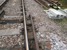
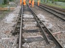
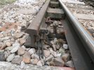
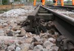
I was on site recently as was stood at a set of trap points with a track circuit interrupter on them, so I took a few photos. I'm not signalling, so I have no idea if this is an insulated or uninsulated one, nor how you would tell the difference by looking at it (someone please explain as I'd love to learn this myself), but here you go:
 

Attachments

  • 2023-05 Track circuit interrupter (1).JPG
    2023-05 Track circuit interrupter (1).JPG
    3.2 MB · Views: 72
  • 2023-05 Track circuit interrupter (2).JPG
    2023-05 Track circuit interrupter (2).JPG
    3.2 MB · Views: 74
  • 2023-05 Track circuit interrupter (3).JPG
    2023-05 Track circuit interrupter (3).JPG
    3.1 MB · Views: 71
  • 2023-05 Track circuit interrupter (4).JPG
    2023-05 Track circuit interrupter (4).JPG
    383.4 KB · Views: 73

alxndr

Established Member
Joined
3 Apr 2015
Messages
1,690
I was on site recently as was stood at a set of trap points with a track circuit interrupter on them, so I took a few photos. I'm not signalling, so I have no idea if this is an insulated or uninsulated one, nor how you would tell the difference by looking at it (someone please explain as I'd love to learn this myself), but here you go:
There's a plastic insulation piece between the main body of the interrupter and the rail. I've marked this up on one of your photographs in yellow. There's also (not visible) an insulating ferrule surrounding the bolt that goes through the web of the rail and an insulated washer behind the nut that holds the interrupter onto the rail. I've marked these in green.

Note that it's not a great example of an installation with the use of the L-shaped brackets to terminate the cables. Those brackets should only be used to connect track circuit tail cables to the rail and not onto the interrupter.

The vast majority of interrupters that you'll come across these days will be of the insulated type as that is the safer and modern way of doing things.


Insulated interrupter.png
 

Railsigns

Established Member
Joined
15 Feb 2010
Messages
2,754
I was on site recently as was stood at a set of trap points with a track circuit interrupter on them, so I took a few photos. I'm not signalling, so I have no idea if this is an insulated or uninsulated one, nor how you would tell the difference by looking at it (someone please explain as I'd love to learn this myself), but here you go:
Generally, a non-insulated interrupter will have one cable connected to it, whereas an insulated one will have two.
 

Signal Head

Member
Joined
26 May 2013
Messages
460
Generally, a non-insulated interrupter will have one cable connected to it, whereas an insulated one will have two.

There's a plastic insulation piece between the main body of the interrupter and the rail. I've marked this up on one of your photographs in yellow. There's also (not visible) an insulating ferrule surrounding the bolt that goes through the web of the rail and an insulated washer behind the nut that holds the interrupter onto the rail. I've marked these in green.

Note that it's not a great example of an installation with the use of the L-shaped brackets to terminate the cables. Those brackets should only be used to connect track circuit tail cables to the rail and not onto the interrupter.

The vast majority of interrupters that you'll come across these days will be of the insulated type as that is the safer and modern way of doing things.


View attachment 135685

Appearances aren't everything - I have a photo of an interrupter complete with insulation piece fitted, and two cables, yet it was uninsulated. Why, because one of the cables was terminated on the same rail the interrupter was fixed to.

I'm guessing that because interrupters are always supplied with insulations, they just get fitted regardless.

In fact, most of the uninsulated ones I have seen have had two cables, because the metallic contact between the rusty interrupter and the rusty rail web is a source of a high resistance fault which could fail the TC, so there is often a short piece of jumper cable bypassing the physical connection, terminated in the rail with the usual channel pin, or 'L plate' to give a sound electrical connection.
 
Status
Not open for further replies.

Top