• Our new ticketing site is now live! Using either this or the original site (both powered by TrainSplit) helps support the running of the forum with every ticket purchase! Find out more and ask any questions/give us feedback in this thread!

Triple yellows V flashing greens

Status
Not open for further replies.

Egg Centric

Established Member
Joined
6 Oct 2018
Messages
2,881
Location
Land of the Prince Bishops
Seen in another thread that the GER had triple yellow aspects.

What prompted the use of flashing greens in the 140mph signalling trial north of Peterborough rather than triple yellows? Indeed why don't we see triple yellows anywhere now? They seem a logical aspect to me.
 
Sponsor Post - registered members do not see these adverts; click here to register, or click here to log in
R

RailUK Forums

Gaelan

Member
Joined
3 Apr 2023
Messages
1,002
Location
Edinburgh
A complete guess, but I wonder if they were worried about it being too hard to distinguish double/triple yellow from a distance.
 

Benjwri

Established Member
Joined
16 Jan 2022
Messages
3,303
Location
Bath
Also higher cost of having an extra light on every signal at a guess?
 

Darandio

Established Member
Joined
24 Feb 2007
Messages
11,141
Location
Redcar
Seen in another thread that the GER had triple yellow aspects.

What prompted the use of flashing greens in the 140mph signalling trial north of Peterborough rather than triple yellows? Indeed why don't we see triple yellows anywhere now? They seem a logical aspect to me.

Back then you would have had to replace the current equipment with 5 bulb heads.
 

Taunton

Veteran Member
Joined
1 Aug 2013
Messages
12,281
I think you are misreading the comments about the former signals on the GEML, they would have multiple double yellows in sequence, and very close together, rather than triple yellow. A sequence might thus run G-YY-YY-YY-Y-R. Line speed under G, drop down to 50 or so under YY. The emus could pull up quite straightforwardly in the distance between sighting single Y and R.
 

etr221

Established Member
Joined
10 Mar 2018
Messages
1,597
The early 1930s LMSR Mirfield speed signalling installation used Yellow over Green in advance of Yellow over Yellow - in both cases above a Red (and at junctions, a seperate red marker light) - so, approaching a Danger/Stop indication, the sequence was G - YGR - YYR - YR - RR. It was very much non-standard: in 1959, it was made slightly less slow, when Y over G aspects were changed to a conventional (?) pair of yellows (but the extra reds remained, until relatively recent resignalling on conventional principle swept all the idiosyncracies away)

I don't know if Y over G was used anywhere else (in the UK).
 

Taunton

Veteran Member
Joined
1 Aug 2013
Messages
12,281
The early 1930s LMSR Mirfield speed signalling installation used Yellow over Green in advance of Yellow over Yellow - in both cases above a Red (and at junctions, a separate red marker light) - so, approaching a Danger/Stop indication, the sequence was G - YGR - YYR - YR - RR. It was very much non-standard: in 1959, it was made slightly less slow, when Y over G aspects were changed to a conventional (?) pair of yellows (but the extra reds remained, until relatively recent resignalling on conventional principle swept all the idiosyncracies away)

I don't know if Y over G was used anywhere else (in the UK).
That was standard USA signalling (where the 1930 Mirfield experimental kit was supplied from), and can still be commonly seen over there where "Green over Red" is a mainstream aspect for full speed over a junction, with various other combinations of lights for other turnout configurations and speeds. There's considerable logic to it, just a different logic.
 

Tester

Established Member
Joined
5 Jul 2020
Messages
1,703
Location
Watford
Seen in another thread that the GER had triple yellow aspects.

What prompted the use of flashing greens in the 140mph signalling trial north of Peterborough rather than triple yellows? Indeed why don't we see triple yellows anywhere now? They seem a logical aspect to me.
An important consideration was that the flashing green was only relevant to >125mph operation. Any non 140mph train simply treated all greens the same, which is much easier to manage operationally, as well as being simpler engineering wise.
 

eldomtom2

On Moderation
Joined
6 Oct 2018
Messages
2,386
There's considerable logic to it, just a different logic.
It's basically an evolution of the "one signal head per road" logic present in the UK with semaphore signals, that we abandoned for position indicators with the introduction of colour lights. US speed signalling at junctions takes this principle and reduces the number of signal heads by grouping routes together based on speed. Generally on plain line without junctions there'll only be one signal head, with a typical progression being green-flashing yellow-yellow-red. Obviously there have been evolutions and this logic has been lost a little, but the general idea is still clearly present.
For junctions universal US practice, regardless of whether route or speed signalling is being used, is to stack the signal heads vertically, unlike in the UK where semaphore signals at junctions are sorted horizontally.
However, the LMS did not use this logic at junctions between routes, instead reverting to standard British practice of signal heads placed horizontally. Signals for switching between the Fast and Slow lines did use US practice, however.
 

TSG

Member
Joined
10 Aug 2020
Messages
207
Location
Somewhere in the South of England
Not sure what you are saying but if that is meant to mean an invalid aspect then you are wrong.

The scenario I refer to is a valid aspect and have a very specific meaning where these are found.
Trainstop arm not proved down

Anyway, a lot cheaper to fiddle with the circuits than fiddle with the circuits and change the heads is why flashing green
 

D7666

Member
Joined
12 Aug 2013
Messages
997
What prompted the use of flashing greens in the 140mph signalling trial north of Peterborough rather than triple yellows?
I think the simple answer to that one is three yellows would have required a different type of signal head as no 4 lamp Y-G-Y-R four aspect signal could display 3 yellows nor could the equivalent (and obsolete) 2 lamp electro mechanical searchlight signal. Whereas the flashing circuity was already in use for flashing yellows, all they need do was apply that to the green.
Don't forget all that occurred in the BR maximum economy days, with the whole point of 140 mph flashing green being the cheap solution. There were no LED signals then capable of multi colours, but even then you still need a three lamp unit whereas in general YGYR 4-lamp heads get replaced by 2-lamp LED heads.
Trainstop arm not proved down
Correct.

The most obvious main line location is Harrow / Amersham- and Chilterns etc obey such aspects. They are of course found elsewhere across LT LU signalling.

TBH I was expecting a substantial amount of wibble answers for that one. Go to the top of the class and add a star to your chart.

== Doublepost prevention - post automatically merged: ==

Trainstop failed?
Well I'd expect you to get that one !!!! Can't award you a class star since you almost wrote the set text book.;)

Like I said, I was predicting a lot of wibble answers to it.
 
Last edited:

Tester

Established Member
Joined
5 Jul 2020
Messages
1,703
Location
Watford
A bit off topic, but as we're talking about green over red.....

In some speed signalling systems, e.g. Victoria, Australia, green over red is the least restrictive aspect - proceed at line speed.

If you grow up with British signalling, it takes a lot of getting used to!
 

godfreycomplex

Established Member
Joined
23 Jun 2016
Messages
1,751
Not sure what you are saying but if that is meant to mean an invalid aspect then you are wrong.

The scenario I refer to is a valid aspect and have a very specific meaning where these are found.
“That’s a doozy” usually means “that’s a very good question”
 

Belperpete

Established Member
Joined
17 Aug 2018
Messages
3,642
An important consideration was that the flashing green was only relevant to >125mph operation. Any non 140mph train simply treated all greens the same, which is much easier to manage operationally, as well as being simpler engineering wise.

The flashing greens were never intended to be a permanent solution for running >125mph trains, it was just a cheap and easy fix to allow experimental >125 mph running on an existing line, without impacting on the standard services. So, as Tester says, standard services could just treat flashing greens in the same way as steady greens.

A failure of the flasher leads the flashing green to show steady green, which has no impact on standard services. Whereas a failure of one aspect of a triple yellow would lead to it showing double yellow, which would impact on the running of standard services. And they would have had to give an AWS warning at the triple yellows, so your regular service trains would be getting a lot of unnecessary AWS warnings.

A signal head capable of showing triple yellow would have needed to be much taller than a 4-aspect head, to maintain spacing between the yellow aspects. A traditional 4-aspect head has the green aspect between the two yellow aspects to give adequate spacing between the two yellows (modern LED signals still have this increased spacing between the two yellows). So to show triple-yellow, you would have needed a head an extra two lamps high (R/Y/G/Y/-/Y). Fitting such a head in place of an existing R/Y/G/Y head would have sighting implications, as the new top yellow aspect could be obscured by bridges, OHLE, etc. Whereas the flashing green solution avoided this as it used standard R/Y/G/Y heads.

 

Benjwri

Established Member
Joined
16 Jan 2022
Messages
3,303
Location
Bath
So to show triple-yellow, you would have needed a head an extra two lamps high (R/Y/G/Y/-/Y). Fitting such a head in place of an existing R/Y/G/Y head would have sighting implications, as the new top yellow aspect could be obscured by bridges, OHLE, etc. Whereas the flashing green solution avoided this as it used standard R/Y/G/Y heads.
Although I agree it’s a messy solution, given standards and training would have to change anyways would it not be easier to go Y/R/Y/G/Y, therefore eliminating the blank space.

Although I’m not an expert I didn’t think there needed to be a blank space regardless, given new LED signals commonly display all 4 aspects from 2 head, including on the ECML, and therefore it could be achieved with 3 heads.
 

Belperpete

Established Member
Joined
17 Aug 2018
Messages
3,642
Although I agree it’s a messy solution, given standards and training would have to change anyways would it not be easier to go Y/R/Y/G/Y, therefore eliminating the blank space.

Although I’m not an expert I didn’t think there needed to be a blank space regardless, given new LED signals commonly display all 4 aspects from 2 head, including on the ECML, and therefore it could be achieved with 3 heads.
The red aspect is always the bottom aspect (with a few very rare exceptions) to avoid snow build up from the hoods of aspects below. The red aspect is also the aspect best aligned with the driver's line of vision. So Y/R/Y/G/Y as a replacement for R/Y/G/Y would not have been allowed.

LED signals weren't available at the time the line was signalled for the high-speed trials. However, as I noted in my previous post, LED signals still include a gap between the two yellow aspects. So you are right that it could be achieved with three heads, but the gap between the heads would still mean it would be taller than the existing head. And you would still have the problem with the failure modes and AWS warnings that I mentioned previously.
 

eldomtom2

On Moderation
Joined
6 Oct 2018
Messages
2,386
A signal head capable of showing triple yellow would have needed to be much taller than a 4-aspect head, to maintain spacing between the yellow aspects. A traditional 4-aspect head has the green aspect between the two yellow aspects to give adequate spacing between the two yellows (modern LED signals still have this increased spacing between the two yellows). So to show triple-yellow, you would have needed a head an extra two lamps high (R/Y/G/Y/-/Y). Fitting such a head in place of an existing R/Y/G/Y head would have sighting implications, as the new top yellow aspect could be obscured by bridges, OHLE, etc. Whereas the flashing green solution avoided this as it used standard R/Y/G/Y heads.
As an aside, since the topic of foreign signalling has already come up in this thread, the general Japanese method of five-aspect signalling is as follows:
  • Lights on the signal head are placed, from top to bottom, Y-Y-R-Y-G
  • The Signal aspect order is G-YG-Y-YY-R
This is, of course, a generalisation - there are various local differences, two other aspects (GG and flashing YG) that see use only in specific places, and not every signal is capable of displaying all five aspects - my general impression is that YG and YY are used only where deemed necessary due to traffic/sighting/etc.
 

Class 170101

On Moderation
Joined
1 Mar 2014
Messages
8,661
The early 1930s LMSR Mirfield speed signalling installation used Yellow over Green in advance of Yellow over Yellow - in both cases above a Red (and at junctions, a seperate red marker light) - so, approaching a Danger/Stop indication, the sequence was G - YGR - YYR - YR - RR. It was very much non-standard: in 1959, it was made slightly less slow, when Y over G aspects were changed to a conventional (?) pair of yellows (but the extra reds remained, until relatively recent resignalling on conventional principle swept all the idiosyncracies away)
Why not just G - YG (Green top bulb, Yellow lower bulb) - YY - Y - R?
 

edwin_m

Veteran Member
Joined
21 Apr 2013
Messages
28,665
Location
Nottingham
Although I agree it’s a messy solution, given standards and training would have to change anyways would it not be easier to go Y/R/Y/G/Y, therefore eliminating the blank space.
This was never intended to be a permanent solution - the Inspectorate would never have allowed routine running about 125mph without some form of train protection. If 140 had ever happened in normal service, then they might just have left the signals with four aspects and relied on whatever that system was to display the fifth aspect in the cab only.

So to support the testing it was best to make the minimum change possible, particularly to have the minimum of impact on drivers who weren't involved in the high speed trial. I assume they were just given an instruction to treat flashing green the same as a normal green.

Given the hazard of a test train failing to brake in time, were there any rules such as having a second driver present during these tests to observe the signals?

Worth noting that this was the same ECML section where Mallard set the world steam speed record. The crack LNER expresses were worked by "double blocking", not being allowed to pass into a section until both that and the following section were clear. Which is kind of a low-tech version of the same thing.
 

martin2345uk

Established Member
Joined
21 Sep 2011
Messages
2,401
Location
Essex
Also what AWS indication would a flashing green have given? To 140mph trains was it technically a restrictive aspect as it meant reduce speed to 125?
 

jp4712

Member
Joined
1 May 2009
Messages
561
Location
Lichfield
Also what AWS indication would a flashing green have given? To 140mph trains was it technically a restrictive aspect as it meant reduce speed to 125?
No, flashing green is the least restrictive aspect: flashing green and steady green both give a 'clear' AWS tone.

If anyone fancies giving it a go, the game Train Sim World 4 has a route Peterborough - Doncaster which includes this stretch of line and includes the flashing green length.
 

martin2345uk

Established Member
Joined
21 Sep 2011
Messages
2,401
Location
Essex
Ah sorry yes got that the wrong way round, steady green in effect being “restrictive” but yes, that makes sense
 

D7666

Member
Joined
12 Aug 2013
Messages
997
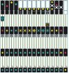
Czech railways signalling sequence.

Obviously this does not apply everywhere; AFAIK this is the standard sequence you get if the train cab is equipped with their old cab signalling safety system (zilch to do with ETCS or anything else this century) - it will vary with different junction layouts.

Image is from the Rule Book. Read it as the left most sequence there is a train two signals ahead, hence the middle row signal is red; left to right the next 10 sequences are increasingly less restrictive (the 12 = 120 km/h); the next ones with the whites I /think/ is some sort of working we would call permissive but the rules are not as our rules are, not directly equivalent.

Note 2 different flash cadences.
 

Attachments

  • cs speed signal sequence.jpg
    cs speed signal sequence.jpg
    102.4 KB · Views: 70
Last edited:
Status
Not open for further replies.

Top