• Our new ticketing site is now live! Using either this or the original site (both powered by TrainSplit) helps support the running of the forum with every ticket purchase! Find out more and ask any questions/give us feedback in this thread!

Sanity-check for a very large-scale rail concept

Status
Not open for further replies.

Destroyer500

Member
Joined
10 Apr 2026
Messages
9
Location
Greece
I’m trying to sanity-check a very large-scale rail concept and would appreciate input from people familiar with contact mechanics / heavy rail.

Concept:
A massive rail vehicle with the following parameters(these are for 1 car only total train will be 24cars and the project is set on 1900-1910max (also instead of a rigid single car each car will be articulated comprising of 5 sections 300m long each 220m wide and 200m tall to allow for turning at <2km radius and all these sections will be conected via giant 60m wide pins)):

  • Total mass (including wheels): 18 million tons
  • Length: 1820 m
  • Width: 220 m
  • Height: 200 m
Running gear:

  • 9 bogies
  • Each bogie: 4 rows × 5 axles × 2 wheels = 40 wheels
  • Total wheels: 360
Wheel geometry:

  • Diameter: 40 m (radius 20 m)
  • Width: 6 m
  • Spoked steel wheels (early 1900s-level materials/manufacturing)
Track:

  • Rails: 6 m wide × 6 m tall
  • Gauge: 100 m with multiple parallel rails (10 total)
  • Assumed steel similar to ~1900–1910 rail steel

What I’ve calculated so far:

  • Load per wheel ≈ 3.9 × 10⁸ N
  • Using Hertzian line contact (cylinder on flat):
    • Contact half-width ≈ 0.085 m
    • Contact area ≈ ~1 m²
    • Peak Hertz stress ≈ 700–800 MPa (static)
With a compliant layer:

  • Stress drops to ≈ ~550 MPa
Dynamic amplification (×1.5–2):

  • Up to ~750–1000+ MPa

My understanding / assumptions:

  • Historical railways operated with Hertzian contact stresses in the 600–1000 MPa range
  • Therefore, these stress levels seem to be within historical precedent
  • The very large rail cross-section should eliminate global bending / structural issues

Where I’m unsure (main questions):

  1. Is it valid to compare these Hertz stresses directly to historical railways, given the much larger contact patch (~1 m² vs cm² scale)?
  2. Would wear / rolling contact fatigue scale similarly, or does the much larger stressed volume fundamentally change behavior?
  3. Does the 6 m × 6 m rail cross-section meaningfully mitigate contact-related damage, or is it mostly irrelevant to surface effects?
  4. With early 1900s steel:
    • Is ~700-800 MPa static / ~1000-1200 MPa dynamic Hertz stress realistically sustainable?
    • Or would this lead to rapid plastic deformation / failure?
  5. Would adding a compliance layer (rubber/laminated interface) make this system viable from a contact stress perspective?

I’m not concerned with practicality or cost — just whether the contact mechanics and material behavior are physically reasonable at this scale.

Would appreciate any corrections, especially if I’m misapplying Hertz theory or misunderstanding how scaling affects wear/fatigue.

Edit;Instead of a 9 bogies carrying 40m diameter wheels system i change to 30+ bogies carrying 10m diameter wheels

Edit 2;Assume 1400 wheels per car each one being 10m in diameter and 6m wide and wheels with no conicity

Edit 3;Lateral guidance system:

  • Side rollers mounted along the vertical faces of each rail
  • Rollers are flat (no flanges) and only engage under lateral drift or during curves
  • Rollers roll along the rail in the direction of travel (no sliding)
Assumed roller configuration:

  • Roller diameter: 1.0 m
  • Roller width: 0.5 m
  • Spacing: ~10 m along each rail
  • 180 roller stations per rail
  • Each station has 2 rollers (one on each side)
  • Total rollers in the system: 3600
Since theres no conicity on the wheels rollers will do the job of steering and self centering on curves
 
Last edited:
Sponsor Post - registered members do not see these adverts; click here to register, or click here to log in
R

RailUK Forums

etr221

Established Member
Joined
10 Mar 2018
Messages
1,603

Destroyer500

Member
Joined
10 Apr 2026
Messages
9
Location
Greece

Crithylum

Member
Joined
21 May 2024
Messages
343
Location
London Borough of Ealing
If I understand correctly, you have assumed that the wheels are cylinders on a flat rail? This is extremely problematic in terms of vehicle dynamics (especially when considering they are 6m wide). The axleboxes/bearings are also going to be under extreme stress which would also need to be considered.

Overall, something this scale is simply not practical, given the square-cube law. Area (and strength) scales with length squared whereas volume (and mass/weight) scales with length cubed.
 

Acathater

Member
Joined
11 Dec 2025
Messages
725
Location
NorthWest
Overall, something this scale is simply not practical, given the square-cube law. Area (and strength) scales with length squared whereas volume (and mass/weight) scales with length cubed.
except as it scales you can make the components hollow.......hollow axles, hollow wheels, and lightweight composite structures are easier on a large scale -also think aircraft structures and wind turbines.
With the correct materials it need not be as heavy as you think

== Doublepost prevention - post automatically merged: ==

Is this to lift ships over the Hormuz peninsular (if that's the correct nomenclature)?
 
Last edited:

BayPaul

Established Member
Joined
11 Jul 2019
Messages
1,517
Not particularly commenting on the physics, but the ratios seem a bit inefficient. Having a 300m long, 200m wide articulated section on 100m gauge track you are going to lose massive amounts of space at the ends of each carriage.

I assume this is in order to have sufficient bogies to support the weight of the carriage?

I would be more inclined to a system similar to that used on crane wheels, where multiple bogies are cantilevered off a single point like in this picture. https://share.google/2TZz9mTrYt9DZiSdp That should give a longer carriage the opportunity to turn corners!

One slight concern I also have over the articulated nature of the train is that when it goes around a corner, all of the weight is transferred to one side (as the mid body of the carriage hangs over the inside of the turn). A more conventional carriage doesn't have this issue - the middle of the carriage hangs over the inside of the track, but the ends hang over the outside.

For practicality, I'd also suggest that even spacing of your 10 rails might be a mistake. Having maybe 9 rails in 3 groups of 3 (or 8 rails in 2 groups of 4) would probably make points easier, mean simpler bogie design on your train, and would more easily allow streets, or farms in the 'four foot'.
 

Destroyer500

Member
Joined
10 Apr 2026
Messages
9
Location
Greece
If I understand correctly, you have assumed that the wheels are cylinders on a flat rail? This is extremely problematic in terms of vehicle dynamics (especially when considering they are 6m wide). The axleboxes/bearings are also going to be under extreme stress which would also need to be considered.

Overall, something this scale is simply not practical, given the square-cube law. Area (and strength) scales with length squared whereas volume (and mass/weight) scales with length cubed.
I realized as well that this is a problem and i redid the calculations for 1:35 conicity on the wheels and hertzian stresses go to something like 700-800mpa.I also went from 9 bogies of 40m diameter wheels to 30+ bogies of 10m diameter for better stress spread

== Doublepost prevention - post automatically merged: ==

Not particularly commenting on the physics, but the ratios seem a bit inefficient. Having a 300m long, 200m wide articulated section on 100m gauge track you are going to lose massive amounts of space at the ends of each carriage.

I assume this is in order to have sufficient bogies to support the weight of the carriage?

I would be more inclined to a system similar to that used on crane wheels, where multiple bogies are cantilevered off a single point like in this picture. https://share.google/2TZz9mTrYt9DZiSdp That should give a longer carriage the opportunity to turn corners!

One slight concern I also have over the articulated nature of the train is that when it goes around a corner, all of the weight is transferred to one side (as the mid body of the carriage hangs over the inside of the turn). A more conventional carriage doesn't have this issue - the middle of the carriage hangs over the inside of the track, but the ends hang over the outside.

For practicality, I'd also suggest that even spacing of your 10 rails might be a mistake. Having maybe 9 rails in 3 groups of 3 (or 8 rails in 2 groups of 4) would probably make points easier, mean simpler bogie design on your train, and would more easily allow streets, or farms in the 'four foot'.
My initial plan was a rigid 1.5km long car but that hit some turn limits that were unacceptable (multi kilometer turns) so i chose an articulated version instead so that turns of 1-2km radius are possible.The car became 1.8km long because theres giant 60m diameter pins being held by 20m rings in place and since theres 4 of them connecting each section 4X80=320m+1500m=1820m.Also the non articulated car would have problems with gradients and would require extemely smooth increase in gradient that again was not acceptable (multiple kilometers for even 1% and basically impossible to reach something like 3%).

The cantilever of a single point idea like cranes wheels sounds interesting but how am i going to transmit power to the wheels ? Dont i need axles ? The idea is that this train will have a few thousand steam or diesel engines powering electric motors all along its length (i thought of having just a few cars be "engine cars" but that would decrease traction substantially so in the end i decided that its better to distribute engines everywhere along with electric transmision (creating basically a steam electric or diesel electric train))

I dont understand the concern about articulation that you mention so please explain further.

One of the reasons i propose that many rails is so that the massive load is distributed as evenly as possible.Decreasing rail count would increase load per wheel a lot.After all with 10 rails i can have 5 groups of 2 and while yes complex as i said it distributes load better.
 
Last edited:

Pigeon

Member
Joined
8 Apr 2015
Messages
1,123
The cantilever of a single point idea like cranes wheels sounds interesting but how am i going to transmit power to the wheels ? Dont i need axles ? The idea is that this train will have a few thousand steam or diesel engines powering electric motors all along its length (i thought of having just a few cars be "engine cars" but that would decrease traction substantially so in the end i decided that its better to distribute engines everywhere along with electric transmision (creating basically a steam electric or diesel electric train))

Individual motor drives for each wheel. You're more than likely better off without axles so you don't have to consider wind-up.

I dont understand the concern about articulation that you mention so please explain further.

With articulation the pivot axis is right at the end of the vehicle, so on a curve the entire length of the vehicle, being between those axes, overhangs on the inside of the curve. With conventional bogies the pivot axis is some distance in from the end of the vehicle, so the body length outside the pivot axes overhangs on the outside of the curve and helps counterbalance the length between axes overhanging on the inside.

What gets me about this concept (that hasn't been mentioned yet) is the requirement to use 1900-1910 level metallurgy. Not only does that multiply the engineering difficulties of a project that would be tough now, it also multiplies the difficulties of simply getting hold of the materials on that sort of scale. And the payloads. A train that can carry half a year's exports from the South Wales coalfield in one go is surely going to struggle to fill itself with anything.
 

Destroyer500

Member
Joined
10 Apr 2026
Messages
9
Location
Greece
Individual motor drives for each wheel. You're more than likely better off without axles so you don't have to consider wind-up.
If I don’t use axles, that would mean I’d need over 1,000 electric motors to power the new design—more than 30 bogies with 10-meter-diameter wheels, resulting in over 1,000 wheels in total per train car.


The vehicle wouldn’t be articulated only at its ends, but along its entire length, if that makes sense. I’ll share a picture that shows this more clearly. The dome is basically the “control center,” and the poles with the wires are telegraph lines—but ignore that part and focus on the articulation.View attachment 202201

Those giant pins, held by the rings, would rest on top of the bogies. Keep in mind that what we’re discussing here is just a single car, not even the entire train.
 
Last edited:

Pigeon

Member
Joined
8 Apr 2015
Messages
1,123
If I don't use axles, that would mean I'd need over 1,000 electric motors to power the new design - more than 30 bogies with 10-meter-diameter wheels, resulting in over 1,000 wheels in total per train car.

If you're making turns of <2km radius with so wide a gauge as 100m as part of normal running you are going to need to allow the wheels to rotate at different speeds across the width. You'll also need laterally independent suspension to be sure of more than two wheels touching the rail. Both of these are much easier to arrange if you don't have a rigid axle trying to make them not happen. As far as I know it is the usual practice on multi-rail systems for moving extreme loads to use either multiple individually-driven wheels or multiple two-wheel axles.

The vehicle wouldn't be articulated only at its ends, but along its entire length, if that makes sense. I'll share a picture that shows this more clearly. The dome is basically the "control center," and the poles with the wires are telegraph lines - but ignore that part and focus on the articulation.View attachment 202201

Those giant pins, held by the rings, would rest on top of the bogies. Keep in mind that what we're discussing here is just a single car, not even the entire train.

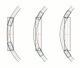
All else being equal that makes things even worse - see attached sketch comparing the overhangs of a conventional carriage, a conventional articulated carriage and a big-rings-and-pins carriage, all of the same size and on the same curvature. You gain a bit by having those very short stubby carriage-lets but you pretty much lose it again by having the pivot points hung outboard of the ends of the carriage body.

You also get some fearsome bending and shear stresses in the necks of those rings which will call for a massive cantilever structure, and dealing with vertical curvature is going to be interesting.
 

Attachments

  • overhangs.png
    overhangs.png
    20 KB · Views: 8

Destroyer500

Member
Joined
10 Apr 2026
Messages
9
Location
Greece
If you're making turns of <2km radius with so wide a gauge as 100m as part of normal running you are going to need to allow the wheels to rotate at different speeds across the width. You'll also need laterally independent suspension to be sure of more than two wheels touching the rail. Both of these are much easier to arrange if you don't have a rigid axle trying to make them not happen. As far as I know it is the usual practice on multi-rail systems for moving extreme loads to use either multiple individually-driven wheels or multiple two-wheel axles.
Ok then ill go with individually driven wheels
All else being equal that makes things even worse - see attached sketch comparing the overhangs of a conventional carriage, a conventional articulated carriage and a big-rings-and-pins carriage, all of the same size and on the same curvature. You gain a bit by having those very short stubby carriage-lets but you pretty much lose it again by having the pivot points hung outboard of the ends of the carriage body.

You also get some fearsome bending and shear stresses in the necks of those rings which will call for a massive cantilever structure, and dealing with vertical curvature is going to be interesting.
The image you presented shows a 2 bogie system which is completely impossible for me to implement due to the massive weight of the vehicle.Also the vehicle in the picture is only articulated at its ends compared to mine which contains multiple segments.I simply cannot do without articulation because it would mean multi killometer turns.

I have also calculated the forces that the rings and pin will face with my configuration and they are acceptable.
 
Last edited:
Joined
3 Sep 2020
Messages
180
Location
Dublin
Apparently there are actually plans being touted to dig a way through those mountains, possibly using nuclear bombs....
I believe this story was actually a hoax, which succeeded in fooling at least one prominent US politician. There have, however, been real proposals along these lines in the past; see for example https://en.wikipedia.org/wiki/Project_Plowshare:
Proposed uses for nuclear explosives under Project Plowshare included widening the Panama Canal [and] constructing a new sea-level waterway through Nicaragua nicknamed the Pan-Atomic Canal...
 

Acathater

Member
Joined
11 Dec 2025
Messages
725
Location
NorthWest
I believe this story was actually a hoax, which succeeded in fooling at least one prominent US politician. There have, however, been real proposals along these lines in the past; see for example https://en.wikipedia.org/wiki/Project_Plowshare:
The Russians appear to have actually tried it on a couple of projects: e.g. when they reversed the Aral sea rivers to get water to the north for cotton growing, and when they built some of their internal ship canal network.
No idea how they got round fallout issues - if they did
 

Pigeon

Member
Joined
8 Apr 2015
Messages
1,123
The Russians appear to have actually tried it on a couple of projects: e.g. when they reversed the Aral sea rivers to get water to the north for cotton growing, and when they built some of their internal ship canal network.
No idea how they got round fallout issues - if they did

By being very large.

Turns out it doesn't actually work very well because so much of the excavated volume is wasted; it's easier just to get the bulldozers in and only dig out the bits you actually want. They've got a string of radioactive lakes somewhere or other where they discovered this by experiment. Apparently also though it does work to use a 30kT nuke to shut down an oil well which is gushing uncontrollably. And it's a practical check that all your systems for maintaining your nukes in working order are functioning correctly.

The image you presented shows a 2 bogie system which is completely impossible for me to implement due to the massive weight of the vehicle.Also the vehicle in the picture is only articulated at its ends compared to mine which contains multiple segments.I simply cannot do without articulation because it would mean multi killometer turns.

You misunderstand. It's an exaggerated, diagrammatic sketch with the three vehicle bodies deliberately kept the same size to demonstrate how the overhang changes as the bogie pivot positions are moved in relation to the vehicle body, as per BayPaul's point. It's drawn with a vehicle body of similar proportions to an ordinary carriage simply because that makes it more obvious.

In terms of your "segmented vehicle" the sketch relates to one segment, not the whole thing. Your segments being short and stubby have a proportionately reduced overhang, but the principle of the way the overhang varies with the bogie pivot positions remains the same.

I have also calculated the forces that the rings and pin will face with my configuration and they are acceptable.

The point here is that the structure needed to carry those forces is a lot of extra unnecessary weight stuck onto the ends of each segment with no compensating additional payload capacity; it makes the whole thing a lot heavier, reduces the load you can carry for a given drive power, etc.

A railway vehicle is a bridge; moving the pivots outboard is equivalent to increasing the span of the bridge while keeping the load concentrated in the middle, which requires the bridge structure to become disproportionately heavier to maintain the load capacity.
 

Acathater

Member
Joined
11 Dec 2025
Messages
725
Location
NorthWest
I think so far there's an important point that's been overlooked. Assuming this "train" is for shipping large unit loads the size of a large ship how do you expect to lift and load/unload without breaking the back of whatever you're shifting?
You're going to need simultaneous lift across the whole width and length of the cargo, and the cargo is going to have to be flat bottomed - which may be a problem if it is also intended to work in other modes - such as the sea. The alternative may be to float the cargo in on a very large dry dock, then dropping the water level - but you'd have major corrosion issues with the electrical motors. Or else float the cargo into a giant caisson, which can then be shuttered at both ends and winched onto the "train" But that imposes maximum limits on number / length of cargoes and of course the water doubles at least the mass to be shifted
 

Destroyer500

Member
Joined
10 Apr 2026
Messages
9
Location
Greece
You misunderstand. It's an exaggerated, diagrammatic sketch with the three vehicle bodies deliberately kept the same size to demonstrate how the overhang changes as the bogie pivot positions are moved in relation to the vehicle body, as per BayPaul's point. It's drawn with a vehicle body of similar proportions to an ordinary carriage simply because that makes it more obvious.

In terms of your "segmented vehicle" the sketch relates to one segment, not the whole thing. Your segments being short and stubby have a proportionately reduced overhang, but the principle of the way the overhang varies with the bogie pivot positions remains the same.
Understandable
The point here is that the structure needed to carry those forces is a lot of extra unnecessary weight stuck onto the ends of each segment with no compensating additional payload capacity; it makes the whole thing a lot heavier, reduces the load you can carry for a given drive power, etc.

A railway vehicle is a bridge; moving the pivots outboard is equivalent to increasing the span of the bridge while keeping the load concentrated in the middle, which requires the bridge structure to become disproportionately heavier to maintain the load capacity.
That analogy would be correct if the vehicle were supported only at a few points, like a bridge span.But in my case the load is distributed over ~1400 wheels across 10 rails along the entire 1820 m length.That means the structure is continuously supported, so bending moments are much smaller — it behaves more like a slab on many supports than a bridge with a long span.

== Doublepost prevention - post automatically merged: ==

I think so far there's an important point that's been overlooked. Assuming this "train" is for shipping large unit loads the size of a large ship how do you expect to lift and load/unload without breaking the back of whatever you're shifting?
You're going to need simultaneous lift across the whole width and length of the cargo, and the cargo is going to have to be flat bottomed - which may be a problem if it is also intended to work in other modes - such as the sea. The alternative may be to float the cargo in on a very large dry dock, then dropping the water level - but you'd have major corrosion issues with the electrical motors. Or else float the cargo into a giant caisson, which can then be shuttered at both ends and winched onto the "train" But that imposes maximum limits on number / length of cargoes and of course the water doubles at least the mass to be shifted
Nothing that big gets lifted — it’s always supported and just transferred into place.
 
Last edited:

Pigeon

Member
Joined
8 Apr 2015
Messages
1,123
That analogy would be correct if the vehicle were supported only at a few points, like a bridge span.But in my case the load is distributed over ~1400 wheels across 10 rails along the entire 1820 m length.That means the structure is continuously supported, so bending moments are much smaller - it behaves more like a slab on many supports than a bridge with a long span.

Are you now saying that those segments are also supported by wheelsets underneath the body, and not just on the big rings/pins?
 

AndrewE

Established Member
Joined
9 Nov 2015
Messages
7,350
I think so far there's an important point that's been overlooked. Assuming this "train" is for shipping large unit loads the size of a large ship how do you expect to lift and load/unload without breaking the back of whatever you're shifting?
You're going to need simultaneous lift across the whole width and length of the cargo, and the cargo is going to have to be flat bottomed - which may be a problem if it is also intended to work in other modes - such as the sea. The alternative may be to float the cargo in on a very large dry dock, then dropping the water level - but you'd have major corrosion issues with the electrical motors. Or else float the cargo into a giant caisson, which can then be shuttered at both ends and winched onto the "train" But that imposes maximum limits on number / length of cargoes and of course the water doubles at least the mass to be shifted
The canal inland from Elblag in Poland has a clever way to get round this, admittedly the ship cradles are worked by ropes but having different rails for the front and back keeps the boats roughly level as they go over the hump out of each pound.
 

Destroyer500

Member
Joined
10 Apr 2026
Messages
9
Location
Greece
So how are you going to do that?
it’s supported and slid/rolled into place

== Doublepost prevention - post automatically merged: ==

If I understand correctly, you have assumed that the wheels are cylinders on a flat rail? This is extremely problematic in terms of vehicle dynamics (especially when considering they are 6m wide). The axleboxes/bearings are also going to be under extreme stress which would also need to be considered.

Overall, something this scale is simply not practical, given the square-cube law. Area (and strength) scales with length squared whereas volume (and mass/weight) scales with length cubed.
Actually im going to use wide flat wheels on wide flat rails cause with conicity rail stress numbers become unmanagable
 
Last edited:
Status
Not open for further replies.

Top