Our new ticketing site is now live! Using either this or the original site (both powered by TrainSplit) helps support the running of the forum with every ticket purchase! Find out more and ask any questions/give us feedback in this thread!
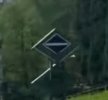
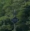
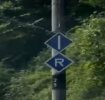
On the line from Dresden to Prague the German 15 kV AC system meets the Czech 3 kV DC system just south of Schöna, on a bridge at 11.86 km. In this direction there seem to be three signals for the driver about the change of systems, two on the German side of the border and two on the Czech side. The four images shew these four signs. The first, second, and fourth seem like the pretty standard ones used on various administrations, but can anyone tell me please what the third, of the two parallel broken horizontal lines, is about, and what the "R" sign mounted with the "pantograph up" sign above it signifies? (And does anyone know of a good description (English or German) of Czech lineside signals and signs, please?)
Not drawn, but delivered back to the overhead lines. When power is recuperated this means that energy recovered when braking is routed back to the overhead lines.
For recuperation to be useful there must be another train in the same section of overhead lines which can make use of this energy, so it wouldn't make much sense to return power while still within the system switch area (which is not connected with the overhead wires on either side of the border)
First a ccorrection: SŽ is Slovenian Railways, not Czech (ČD) (nor Slovak - ŽSR)
My interpretation (based on what's already been) said: the parallel broken lines indicate that the pantograph must be down, either because there is an interruption in the overhead, or it is necessary to raise a different pantograph, or may be for automatic current detection to work.
And the R to indicate that regenerative braking is permitted, on the Czech dc system: my understanding is that with ac, need for phase sysnchrisation means that regeneration is difficult if not impossible.
Thanks for all the comments. And yes, SŽ is indeed now ambiguous as both Slovenian Railways and Správa Železnic, the Czech infrastructure operator. As it says of itself: "Správa železnic (as it is called today) was established as the state organisation under the name Správa železniční dopravní cesty [SŽCD] in 2003 as one of the two successor organisations of stateowned České dráhy [ČSD] of that time. As of 2020, it performs its activities under the name of Správa železnic."
The Czech document referred to looks very interesting, and — with the invaluable assistance of Mr Google — with much information to offer.
I think the question of the "R" is answered as regenerative braking on a DC system — coming northwards there is an "R" with a red diagonal stroke through it just before leaving the Czech system, which would accordingly mean the end of regenerative braking at that point.
I still haven't found anything for the two parallel horizontal broken lines, but I see that in the DB Signalbuch (Richtlinien 301) two parallel horizontal solid lines indicates entry into a DC area. Could the broken lines be a Czech variant? The sign is found just about as DC would be in the OLE. And coming northwards into Germany there is a very washed-out blue diamond sign that looks as if it does have on it the double curve that signifies AC. So that would make sense.
So at this border there seems to be a very short dead section between the panto down and the panto up signs, but nothing to indicate open main circuit-breaker and close main circuit-breaker. Will those operations be performed automatically (though I couldn't see any trackside magnets for doing that), or is it part of the driver's knowledge to know that he has to do that before (and after) dropping and then raising the pantograph. (At least I think D and CZ both use the same 1950 mm panto width!) Wikipedia seems somewhat unhelpful about electrification systems meeting up with one another!
About a year or so ago I came across this Czech YouTube cab video on a southbound train on that section of line which specifically shows how the driver changes voltage. It all appears to be done manually!
Interesting, though admittedly I do not know that much about technical matters. I was there just a day or 2 ago-but as from that day construction works meant it was in a replacement bus on the other side of the river Elbe/Labe.
As an aside: that sprava=construction in CZ is very heavily represented now in most main stations with some form of information-in Praha HN=main even has its own room with pictures, info etc.
This method with 2 panto on 1 loc was, I think, the old form, at that time a big new achievement to be even possible, but as with so many technical things overtaken in time. It was also like that long time ago from NL to BE: from 1500 to 3000 V. From what I know there are more spots within CZ where current is changed.
For recuperation to be useful there must be another train in the same section of overhead lines which can make use of this energy, so it wouldn't make much sense to return power while still within the system switch area (which is not connected with the overhead wires on either side of the border)
So at this border there seems to be a very short dead section between the panto down and the panto up signs, but nothing to indicate open main circuit-breaker and close main circuit-breaker. Will those operations be performed automatically (though I couldn't see any trackside magnets for doing that), or is it part of the driver's knowledge to know that he has to do that before (and after) dropping and then raising the pantograph. (At least I think D and CZ both use the same 1950 mm panto width!) Wikipedia seems somewhat unhelpful about electrification systems meeting up with one another!
There is a neutral catenary section - or just a void, like between NL and BE, each time the voltage, or even phase, of the catenary changes. This is to avoid big damage in case a driver would forget to lower his pantograph. Without neutral section, a raised pantograph would short the two different voltages with immense damage to the power substations. With a neutral section, which is earthed, a raised pantograph will just cause the two substations to trip.
Normally the driver lowers his pantograph when the loco crosses the horizontal line board and raises it back when the vertical line board is met.
Most of the time it is just done manually by the driver. There are a few cases where it is automated : TVM300 and TVM430 have codes for that so TGVs switch automatically if the line is equipped with the suitable beacons. In Paris, at junctions between RATP and SNCF (like in the tunnel between Paris Nord and Chatelet Les Halles, RER B & D), it is automatic also, and per unit, so you can see a MU train going south with its first unit under 1,5 kV DC and the second one still under 25 kV AC.
On Belgian and French multisystem locs, there is a selector, available only when the loco is powered down, named "sélecteur d’administration" that lets the driver choose which system he is using, and will select the correct loco configuration (pantograph, power circuits, motor couplings, signaling system, etc) accordingly. When a pantograph is raised, the loco first "senses" whether the catenary voltage matches the selection made by the driver and trips the loco if not.
On Belgian and French multisystem locs, there is a selector, available only when the loco is powered down, named "sélecteur d’administration" that lets the driver choose which system he is using, and will select the correct loco configuration (pantograph, power circuits, motor couplings, signaling system, etc) accordingly. When a pantograph is raised, the loco first "senses" whether the catenary voltage matches the selection made by the driver and trips the loco if not.
On that note, and talking Belgian locos (although in this case an identical design in Luxembourg): the fire that wrote off CFL 3001 was reportedly due to it having 3000V DC selected when under 25kV AC catenary. Such a protection circuit should prevent that?
On that note, and talking Belgian locos (although in this case an identical design in Luxembourg): the fire that wrote off CFL 3001 was reportedly due to it having 3000V DC selected when under 25kV AC catenary. Such a protection circuit should prevent that?
We are aware of an issue with emails from the Forum to Microsoft-based email accounts (hotmail/outlook/live.com email addresses). This is being looked into currently, thanks for your patience meanwhile.