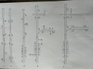
First up, apologies for a long post. But I hope it is of help to anyone who would like to understand signalling. I apologise to anyone who finds it simplistic. I’ve tried to pitch it to anyone.
As mentioned. If you are a driver it’s important to learn each move. Because the railway is inconsistent and it’s not always easy to tell which moves are signalled and which aren’t.
I’ve drawn a few fictitious examples to show what I mean. There are so many connotations that signals can be used in (whilst maintaining an underlying logic) that the rule book doesn’t give more than a basic overview. Only local knowledge can really teach you.
That said. Sticking only to your question as to can you tell from maps? Well, yes, with some signalling knowledge there are clues.
With reference to my basic drawings.
1. Is a simple signalled crossover signalled in both directions using shunt discs. One is left sided, one is right. It doesn’t matter.
The key takeaway (for later) is that from either disc after traversing the crossover you reach a signal.
2. Is just a colour light version of 1. I’ve labelled the distant signals from 1 as R for repeater but they could equally be 3 or 4 aspect signals in a Track circuit block area. Again the key takeaway is that after traversing the crossover you encounter a signal.
3. Is a crossover signalled in both directions. From down to Up you encounter a limit of shunt. From Up to down you reach the platform and there is a signal limiting you.
Without the limit of shunt there could not be a signalled move in that direction.
Without the limiting signal on the platform there could not be a signalled move to the platform (and the signal protecting the crossover would not have a No4 junction indicator).
The crossover would then be an unsignalled crossover and moves could only be done by verbal permission and extra controls put in such as holding trains at signals further back in case the shunting train were to go too far. This would usually be done under local instructions.
Many unsignalled crossovers aren’t interlocked and require clipping and scotching points and handsignals to control the movement.
This is also where communication becomes important. Drivers must know exactly how far their movement can proceed as the protection usually given by the signalling system isn’t there.
Notice in the diagram how due to the crossover being facing Up direction trains can terminate in the Down platform only and return along the Down Main.
(A terminating train requiring to return and receiving a main aspect to the Up platform without the junction indicator would be a wrong route).
4. Is where it gets more complex. But applying the basic logic.
This looks like a signalled crossover. But…..while trains can cross in either direction from signals there are limitations to its use.
The crossover allows;
-Trains from the Down platform to reach the down branch.
-Trains from the Up main or Up Branch to reach the Down platform and terminate (at the fixed Red).
Other trains not using the crossover can move
-From the Up Main or Up Branch to continue along the Up Main.
-From the Down main to continue over the level crossing along the Down main.
Trains cannot.
-Terminate in the Up platform and return to either Down Branch line or Down Main (There is no signal for Down direction movements from the Up platform and no crossover to the Down Main).
(As in figure 3 any terminating Up Branch train or Up Main train would require the No4 junction indicator to take them to the Down platform).
- Arrive on the Down Main in the down platform and use the crossover to cross to the Up Main to return to the station and start back from the Up platform.
This is because there is no signal protecting the level crossing or the signal protecting the level crossing on the Up Main (circled point 1). So a train could cross over to the Up main, plough through the crossing and head on into a train standing at the signal protecting the crossing on the Up Main (or even further along).
-Terminate in the Down platform and use the crossover to access the Up Branch to return to the Up platform. This would require a signal or limit of shunt at circled point 2 (again, to prevent a train simply continuing down the branch head on into another train).
-Terminate in the Down platform and access the Down branch to return to the Up platform. This would require a signal at circled point 3 for movements in the up direction.
As the map stands the following moves are available.
DM to DM
DM to DB
UM to UM
UM to DM (Down platform)
UB to UM
UB to DM (Down platform)
A limit of shunt or fixed red signal at circled point 1 would additionally give.
DM to UM (for replatforming) and allow down trains to terminate and return in the up direction.
A limit of shunt or fixed red signal at circled point two would additionally give.
DM to UB (for replatforming) and allow down trains to terminate and return in the up direction.
A signal at circled point 3 with two possible routes to either platform would give.
DB to UM (allowing replatforming) and allow down trains to terminate and return in the up direction.
But there still wouldn’t be full flexibility. Once any train was in the Up platform it could only leave along the Up main.
To rectify this a signal could be placed at the end of the Up platform (at circled point 4) to allow
UM to DB
UM to UB LOS (circled point 2).
But unless an additional crossover were provided (at circled point 5) the Up platform still couldn’t be used to return trains to the down main.
Without a new crossover but with the additional signal at circled point 4.
They would need to arrive on the Up main then.
Shunt to the new UM LOS at circled point 1 or
Shunt to the new UB LOS at circled point 2 or
move to the Down Branch to return from the new signal at circled point 3
Return to the Down platform then depart along the Down Main.
Let’s say resignalling added all limits of shunts, signals and crossover.
We now have diagram 5.
You then get into further complexity as to what each signal could display. Would the design call for theatre boxes, or junction indicators etc.
So adding our down direction signal on the Up platform at circled point 4 and a new crossover would give 4 possible routes from that signal. As an example that signal could display.
Main aspect only= DM
Main Aspect + Junction Indicator= DB
Position light + XUM to UM LOS
Position light + XUB to UB LOS
(X usually means ‘wrong direction’ when shown in a stencil indicator).
Again, my apologies to anyone (including OP) to whom this is simplistic. But I hope someone finds it interesting).





www.gov.uk