• Our new ticketing site is now live! Using either this or the original site (both powered by TrainSplit) helps support the running of the forum with every ticket purchase! Find out more and ask any questions/give us feedback in this thread!

Pacer/Sprinter Transmitter Amplifier (Cab to Cab/PA phone)

Status
Not open for further replies.

benjistrains

New Member
Joined
10 Aug 2025
Messages
1
Location
Derby
Hello,
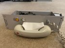
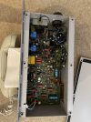
Me and a friend have recently aquired two Whiteley Electronics Transmitting Amplifiers and wondering if there is anyway to get it working outside a unit while using all the original hardware. We can't find any infomation online about any wire diagrams at all meaning we are unable to know what all the electronics do and what voltage they require. The images below show what the phones look like both on the inside and the outside. Any help will be greatly appreciated.
 

Attachments

  • interior of phone.jpg
    interior of phone.jpg
    3.4 MB · Views: 38
  • exterior.jpg
    exterior.jpg
    823.5 KB · Views: 37
  • IMG_3741.jpg
    IMG_3741.jpg
    3 MB · Views: 33
  • IMG_3742.jpg
    IMG_3742.jpg
    737.6 KB · Views: 37
Sponsor Post - registered members do not see these adverts; click here to register, or click here to log in
R

RailUK Forums

satisnek

Member
Joined
5 Sep 2014
Messages
1,097
Location
Kidderminster/Mercia Marina
Ah, good old through-hole components - the kind of electronics I used to work on back in the day. Unfortunately it was nothing like this, which is, it goes without saying, highly specialised.

A good start would be to trace the wires from the connector pins (PL1) - at least there's only five of them. If you can partially remove the PCB enough to see its underside, there should be an obvious ground plane to which the ground pin should be directly connected. Another pin will be a power input (+24V DC? Can anybody confirm that Pacers/Sprinters have 24V DC power?) - this might go to the large capacitor top right (C1) or perhaps D2 - is this a reverse polarity protection diode? Check the working voltage of the electrolytic capacitors - for a 24V supply they will be 50V or 63V types.

I'm guessing that there's a balanced audio line down the length of the train, which is what the transformers at the top left will be for. Is there a pair of wires from these to two connector pins? And the fifth pin is a control/status line???

Good luck!
 
Status
Not open for further replies.

Top