• Our new ticketing site is now live! Using either this or the original site (both powered by TrainSplit) helps support the running of the forum with every ticket purchase! Find out more and ask any questions/give us feedback in this thread!

OLE Block Dropper Spacing

OLEngineer

Member
Joined
10 Jun 2026
Messages
16
Location
London
On dropper schedules, block droppers holding the contact wire and contenary wire are usually placed 9m away from each bridge arm, usually on the entry and exit. This makes sense to me.
What I would like to learn more about is the common practice of installing block droppers either side of the bridge arm, usually 150mm away. I've spoken with senior engineers and CREs at my place of work and everyone just agrees this is how its done, because its always been does this way. Is there any justification for this dimension? These usually dont show up on dropper schedules either, with the extra block droppers being allocated as per. Is there a network rail standard or drawing which references this need? Why 2 block droppers either side of the registration, is 1 not enough? I am keen to learn more!

Just to clarify; by block droppers I mean 0 encumbrance, side by side twin contact wire clamps
 
Sponsor Post - registered members do not see these adverts; click here to register, or click here to log in
R

RailUK Forums

thecrofter

Member
Joined
16 Dec 2011
Messages
287
That's a very specialised question for here. Do you have the excellent book by Garry Keenor on 'Overhead Line Electrification of Railways'? He is the Professional Head of Electrification for AtkinsRealis and knows everything there is to know about the design of OLE/OCS.

You can download a free copy of his tome from:

The book is designed for newcomers and beginners to OLE so probably won't go into the detail you're asking so I would contact Garry directly. He no longer posts on X (Twitter) as his website lists but has a mastodon profile https://mas.to/@25kV - as a self confessed "catenary shagger' (his words not mine!) I'm sure he'd be happy to help.
 

OLEngineer

Member
Joined
10 Jun 2026
Messages
16
Location
London
That's a very specialised question for here. Do you have the excellent book by Garry Keenor on 'Overhead Line Electrification of Railways'? He is the Professional Head of Electrification for AtkinsRealis and knows everything there is to know about the design of OLE/OCS.

You can download a free copy of his tome from:

The book is designed for newcomers and beginners to OLE so probably won't go into the detail you're asking so I would contact Garry directly. He no longer posts on X (Twitter) as his website lists but has a mastodon profile https://mas.to/@25kV - as a self confessed "catenary shagger' (his words not mine!) I'm sure he'd be happy to help.
Good point! I've read through the 6th edition countless times! I keep a copy on my work laptop and personal computer for late night reading :) Good idea on reaching to Garry through Mastodon, I'll look into it!
 

tcp

Member
Joined
10 Jun 2025
Messages
10
Location
UK
I haven't heard of this practice. My understanding is twin contact bridge approach spans allocate a single block dropper. A twin contact bridge span (not approach span) has no block droppers. I don't recall seeing additional block droppers. I think 9m is standard for UKMS and Mk3 (a+b) but as I recall other dimensions exist. I will be keeping an eye out looking for these additional block droppers.
 

OLEngineer

Member
Joined
10 Jun 2026
Messages
16
Location
London
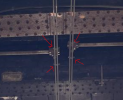
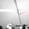
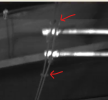
I've only worked on the GWML so possibly different maintenance teams have different rules for their areas. See the attached images for examples I've found only 5 miles from Paddington. The colour image shows wires installed by Crossrail for the Action Dive Under at Acton Yard, so some fairly recent installations. Some only have 1 block dropper and others have 2 so there must be some contention on this topic?
 

Attachments

  • Screenshot 2026-06-12 174036.png
    Screenshot 2026-06-12 174036.png
    140.4 KB · Views: 68
  • Screenshot 2026-06-12 173543.png
    Screenshot 2026-06-12 173543.png
    70.7 KB · Views: 68
  • Capture.PNG
    Capture.PNG
    534 KB · Views: 68

tcp

Member
Joined
10 Jun 2025
Messages
10
Location
UK
I couldn’t picture it before but with the photos it seems to make sense that you would need a block dropper at the bridge arm to support the contact wire, for the arrangement of a single bridge arm with twin contact wire, assuming the single bridge arm supports only one wire. The bridge arm holds the contenary and the block dropper supports the contact. I had assumed on this arrangement the bridge arm held both wires but if not this would make sense.

As for why it’s 150mm, I have no idea, it just seems like a reasonable distance. Close to the bridge arm but with sufficient clearance to the bridge arm.
 

WiredUp

Member
Joined
17 May 2021
Messages
97
Location
Bedford
There is no stated distance in any of the OLE basic design ranges for the block/solid droppers either side of a single bridge arm. The 150mm is effectively a convention which has probably crept in because of an absent dimension on the original drawings produced when Mark 3 equipment was first introduced for the Lea Valley Electrification in the last 1960s's. It looks like someone at BICC forgot to put the dimension on drawing 1/199/142 (allocation 1/199/142/002) and also left it off the assembly drawing (1/111/002) and bridge approach dropper drawing hat you would expect to see in 1/014 (now MS/B14...etc) and 1/199's. I would guess it has never worried anyone so the basic design drawings have never been updated to include it.

If you delve into the detail of the miscellaneous components then a contact wire swivel clip for Mk1 and Mk3 equipment is 72mm long (refer to the oldest version of 1/123/005 available), 150mm or 6" either side of the swivel clip to the twin contact wire clamps (your 125/018/001's) was probably picked as a simple rule of thumb from the first installation and the "measurement" proliferated around for want of absence of information on any of the basic design drawings. It's a conservative measurement well within the 25mm construction tolerances too so even if both twin contact wire clamps were installed a little bit too close to the swivel clip they still wouldn't foul it - and the 150mm provides some allowance for along track movement. One thing to remember is that that quite a bit of Mk3 was carried over Mk1 (all Imperial) and eventually metrified (you can see the evidence of this in the conversion tables in 1/988) so metric values with imperial equivalents were probably the norm. If you want to see the predecessors to the insulated bridge arms then these were the spring loaded and solid arm Mk1 arms types.

In terms of why there are two contact wire clamps installed, as the bridge arm is nominally 9m from the D1 droppers in-span for Mk3 equipment, it would make sense to make the contact/contenary/contact wire swivel clip function as a single "stiff" assembly for reliability, thereby ensuring both wires uplift the same amount to try and avoid any differential wear on them - the effects of cant allowing. 18m worth (2 x 9m CW / Cont.) of contact wire either side of the bridge arm is quite heavy and the non-registered wire would sag quite a bit otherwise. Noting that both wires would be HD Cu of 107mm2 unworn CSA when installed, there is also the issue that if one wire wears more than the other you could get differential creep. Mk3 and Mk3A after all has a lower contact wire tension (8.925 kN nominal) compared to the contenary (11.100kN nominal.)

There isn't any information in the Standards and OLE Working Instructions either as you say so engineers of the past filled in the gaps.

1781468571665.jpeg1781468555547.png
 

OLEngineer

Member
Joined
10 Jun 2026
Messages
16
Location
London
There is no stated distance in any of the OLE basic design ranges for the block/solid droppers either side of a single bridge arm. The 150mm is effectively a convention which has probably crept in because of an absent dimension on the original drawings produced when Mark 3 equipment was first introduced for the Lea Valley Electrification in the last 1960s's. It looks like someone at BICC forgot to put the dimension on drawing 1/199/142 (allocation 1/199/142/002) and also left it off the assembly drawing (1/111/002) and bridge approach dropper drawing hat you would expect to see in 1/014 (now MS/B14...etc) and 1/199's. I would guess it has never worried anyone so the basic design drawings have never been updated to include it.

If you delve into the detail of the miscellaneous components then a contact wire swivel clip for Mk1 and Mk3 equipment is 72mm long (refer to the oldest version of 1/123/005 available), 150mm or 6" either side of the swivel clip to the twin contact wire clamps (your 125/018/001's) was probably picked as a simple rule of thumb from the first installation and the "measurement" proliferated around for want of absence of information on any of the basic design drawings. It's a conservative measurement well within the 25mm construction tolerances too so even if both twin contact wire clamps were installed a little bit too close to the swivel clip they still wouldn't foul it - and the 150mm provides some allowance for along track movement. One thing to remember is that that quite a bit of Mk3 was carried over Mk1 (all Imperial) and eventually metrified (you can see the evidence of this in the conversion tables in 1/988) so metric values with imperial equivalents were probably the norm. If you want to see the predecessors to the insulated bridge arms then these were the spring loaded and solid arm Mk1 arms types.

In terms of why there are two contact wire clamps installed, as the bridge arm is nominally 9m from the D1 droppers in-span for Mk3 equipment, it would make sense to make the contact/contenary/contact wire swivel clip function as a single "stiff" assembly for reliability, thereby ensuring both wires uplift the same amount to try and avoid any differential wear on them - the effects of cant allowing. 18m worth (2 x 9m CW / Cont.) of contact wire either side of the bridge arm is quite heavy and the non-registered wire would sag quite a bit otherwise. Noting that both wires would be HD Cu of 107mm2 unworn CSA when installed, there is also the issue that if one wire wears more than the other you could get differential creep. Mk3 and Mk3A after all has a lower contact wire tension (8.925 kN nominal) compared to the contenary (11.100kN nominal.)

There isn't any information in the Standards and OLE Working Instructions either as you say so engineers of the past filled in the gaps.

View attachment 205992View attachment 205991
Thank you for your comprehensive reply! I really appreciate it!
 

Top