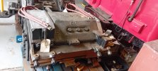
Visited Acton depot museum yesterday, very interesting. Attached picture shows 1938 stock bogie, I think (many exhibits unlabelled as depot collection still being curated we were told. Can anyone explain sets of 4 and 3 red cables please. I know trains ran on dc then, series or parallel, dont understand why not just 2 cables to each motor. Thanks

-
Our new ticketing site is now live! Using either this or the original site (both powered by TrainSplit) helps support the running of the forum with every ticket purchase! Find out more and ask any questions/give us feedback in this thread!
You are using an out of date browser. It may not display this or other websites correctly.
You should upgrade or use an alternative browser.
You should upgrade or use an alternative browser.
LU 1938 stock bogie
- Thread starter bern56
- Start date
- Status
- Not open for further replies.
Sponsor Post - registered members do not see these adverts; click here to register, or click here to log in
R
RailUK Forums
- Joined
- 13 Dec 2018
- Messages
- 4,576
Most motors have electromagnets rather than permanent magnets to provide the magnetic field hence the extra cabling as required for the field coils.Visited Acton depot museum yesterday, very interesting. Attached picture shows 1938 stock bogie, I think (many exhibits unlabelled as depot collection still being curated we were told. Can anyone explain sets of 4 and 3 red cables please. I know trains ran on dc then, series or parallel, dont understand why not just 2 cables to each motor. Thanks

Tunnel Bore
Member
- Joined
- 28 Feb 2016
- Messages
- 57
In some cases, the field winding of a DC motor is in series with the armature winding (common for traction motors), in some cases in parallel so you might only see two wires externally but if you wanted to control the motor, such as inserting starting resistances in series with the armature, or field weakening resistances in parallel with the a series field winding, then you'd likely make all four connections available to run toe the control contactors. Some motors were "compound" with both series and parallel field windings so you might even see six wires.Most motors have electromagnets rather than permanent magnets to provide the magnetic field hence the extra cabling as required for the field coils.
RichardAsh1981
Member
- Joined
- 28 Oct 2017
- Messages
- 251
Also, two motors on the bogie, which can be wired in series or in parallel for lower and higher speeds.
The nearest motor has four wires, so likely two for the commutator and two for the field. This is needed so the control system can reverse the polarity of the field vs. the commutator, which is the only way of reversing a field wound motor.
The far motor then has three wires. It looks like it is one short as there are four bolts but only three cables on the far motor.
If there are two motors on this bogie, then it may not be 1938 stock, because the 1938 stock had one motor per bogie only, so it would fit under the floor. This is confirmed in the book "DC electric trains and locomotives in the British Isles" by R.L. Vickers.
The nearest motor has four wires, so likely two for the commutator and two for the field. This is needed so the control system can reverse the polarity of the field vs. the commutator, which is the only way of reversing a field wound motor.
The far motor then has three wires. It looks like it is one short as there are four bolts but only three cables on the far motor.
If there are two motors on this bogie, then it may not be 1938 stock, because the 1938 stock had one motor per bogie only, so it would fit under the floor. This is confirmed in the book "DC electric trains and locomotives in the British Isles" by R.L. Vickers.
- Joined
- 13 Dec 2018
- Messages
- 4,576
They are almost always series wound but have 4 connections so field can be weakened to obtain a higher speed as you stated.In some cases, the field winding of a DC motor is in series with the armature winding (common for traction motors), in some cases in parallel so you might only see two wires externally but if you wanted to control the motor, such as inserting starting resistances in series with the armature, or field weakening resistances in parallel with the a series field winding, then you'd likely make all four connections available to run toe the control contactors. Some motors were "compound" with both series and parallel field windings so you might even see six wires.
- Status
- Not open for further replies.