• Our new ticketing site is now live! Using either this or the original site (both powered by TrainSplit) helps support the running of the forum with every ticket purchase! Find out more and ask any questions/give us feedback in this thread!

Gradient Help

Status
Not open for further replies.

Andy873

Established Member
Joined
23 Mar 2017
Messages
1,411
I'm trying to work out a gradient and need some help please.

At a particular point, this line swings north utilising the sides of some hills to bring the line to a lower lever.

If the line had carried on (straight) you would have needed to drop from 300 feet to 205 in just half a mile, but how do you work out that gradient? Drop 95 feet in 0.5 miles.

What gradient would this be?

Thanks,
Andy.
 
Sponsor Post - registered members do not see these adverts; click here to register, or click here to log in
R

RailUK Forums

jfollows

Established Member
Joined
26 Feb 2011
Messages
10,096
Location
Wilmslow
Hi Andy,
Simplistically, but I'm not sure you're asking this, 95 feet in 0.5 miles is 95 feet in 2640 feet, or 1 in 28 or so.
 

Mcr Warrior

Veteran Member
Joined
8 Jan 2009
Messages
17,207
Concur with @jfollows.

5280 feet in a mile, so half a mile is 2640 feet.

2640 divided by 95, I believe, gives an approximate gradient of 1 in 28, which, whilst not exceptional, is fairly steep for most railway lines.
 

jfollows

Established Member
Joined
26 Feb 2011
Messages
10,096
Location
Wilmslow
Yes, if the non-straight line is significantly longer than half a mile the equation changes to reduce the gradient.
 

Mcr Warrior

Veteran Member
Joined
8 Jan 2009
Messages
17,207
Yes, if the non-straight line is significantly longer than half a mile the equation changes to reduce the gradient.
Indeed, in that case, you'd need to accurately measure the length of the track that's actually being traversed by the train, not the "as the crow flies" distance from A to B.
 

Rescars

Established Member
Joined
25 May 2021
Messages
2,540
Location
Surrey
If you can find a copy of the line's gradient profile, presumably this will give you an approximate answer and save you some complex calculations.
 

Mcr Warrior

Veteran Member
Joined
8 Jan 2009
Messages
17,207
If you can find a copy of the line's gradient profile, presumably this will give you an approximate answer and save you some complex calculations.
Or failing that, interpretation of old six inch to the mile OS maps may be of assistance. The calculations really aren't / shouldn't be that complicated.

@Andy873. Where's the section of railway that you're looking at? Somewhere in East Lancashire, perhaps?
 

edwin_m

Veteran Member
Joined
21 Apr 2013
Messages
28,637
Location
Nottingham
Concur with @jfollows.

5280 feet in a mile, so half a mile is 2640 feet.

2640 divided by 95, I believe, gives an approximate gradient of 1 in 28, which, whilst not exceptional, is fairly steep for most railway lines.
1 in 28 would require banking of many trains, which would be a major operational inconvenience and cost, so the builder would most likely avoid this unless the avoiding route was extremely expensive to build. Going round a series of hills is probably going to reduce net construction costs, as the extra cost for the longer track will be outweighed by not building deep cuttings or tunnels to go through the hills. So a route that avoids the hills, and also reduces the gradient to something a bit more manageable, would generally be chosen (as it evidently was in the OP's case).
 

ac6000cw

Established Member
Joined
10 May 2014
Messages
3,910
Location
Cambridge, UK
Indeed, in that case, you'd need to accurately measure the length of the track that's actually being traversed by the train, not the "as the crow flies" distance from A to B.
If you can identify the route of the track on Google Maps you can use the 'measure distance' facility with enough intermediate points inserted (just keep clicking on the map) to get a reasonable step-wise approximation to the actual distance. e.g. a fairly extreme example below where the rail distance includes a horseshoe curve followed by a loop over itself, making the rail distance about 2.5 times the straight line distance (and even that amount of added curvature only reduces the gradient down to around 2.2% / 1 in 45 in this instance):

1724576396839.png

...versus in a straight line:

1724576564176.png
 
Last edited:

Magdalia

Established Member
Joined
1 Jan 2022
Messages
7,379
Location
The Fens
If you can find a copy of the line's gradient profile, presumably this will give you an approximate answer and save you some complex calculations.
There is a Gradient Profiles book published by Ian Allan which includes most main lines in Great Britain. Some signal boxes also had gradient profiles for their section of line.

Or failing that, interpretation of old six inch to the mile OS maps may be of assistance. The calculations really aren't / shouldn't be that complicated.
A few words of caution here. Spot heights on OS Maps are accurate, but for most of mapmaking history, contours are only an approximation. Furthermore, railways have cuttings, embankments, viaducts and tunnels: in all of these cases the trackbed won't be at the same level as the contours. Over short distances, such as half a mile, the error margins will be big.

I'm trying to work out a gradient and need some help please.


Where's the section of railway that you're looking at? Somewhere in East Lancashire, perhaps?

The Great Harwood loop is not in the Ian Allan book, but it does have Blackburn to Accrington via Rishton and Accrington to Burnley.

If you are not far away there's no substitute for going to the site to have a look!
 

Andy873

Established Member
Joined
23 Mar 2017
Messages
1,411
Thanks everyone!

So we simply take the distance and divide it up by the height difference. I tried that and got 1 in 27.7 (1 in 28 rounded up) but wasn't sure I was right.

Yes, if the non-straight line is significantly longer than half a mile the equation changes to reduce the gradient.

If you can find a copy of the line's gradient profile, presumably this will give you an approximate answer and save you some complex calculations.
Fortunately I do have a copy of John Marshall's gradient profile of the line.

The route the line was to take was to swing north and then take a large sweeping right. This reduced the decent to a 1 in 52 over three quarters (or so) of aa mile.

I can see why this route was chosen now, if the L&Y had gone the more direct route you would have had to build embankments on flood land- not a great idea. You would need then to gain some height to cross over the river calder.

Where's the section of railway that you're looking at? Somewhere in East Lancashire, perhaps?
Yes, my old branch.

If you look at the following OS hills map (1896) from the NLS website, find Gt. Harwood station and follow the track east (right direction), you'll see where the line swings north.


What the L&Y did was (as said) use the sides of the hills together with a series of embankments to reach Martholme Viaduct (over the river Calder).

the builder would most likely avoid this unless the avoiding route was extremely expensive to build.
Good point, this eventual route though, wasn't cheap, Martholme viaduct (in today's money) cost 2 million, and that's just the viaduct.

The Great Harwood loop is not in the Ian Allan book, but it does have Blackburn to Accrington via Rishton and Accrington to Burnley.

If you are not far away there's no substitute for going to the site to have a look!
I would if I could, but that's not practical for me but thanks.
 

edwin_m

Veteran Member
Joined
21 Apr 2013
Messages
28,637
Location
Nottingham
Good point, this eventual route though, wasn't cheap, Martholme viaduct (in today's money) cost 2 million, and that's just the viaduct.
If they'd taken the straight route across the flood plain, they would have been at a similar elevation above the Calder so whatever crossing was built would have been at roughly the same height as the viaduct they actually did build. Above a certain height, a viaduct becomes cheaper than an embankment, which must have been the case at Martholme (unless there was some other factor such as land ownership) otherwise they would just have built an embankment and a bridge. So, in all probability, the direct route would have needed a much longer viaduct over the entire flood plain as seen, for example, at Harringworth.
 

30907

Veteran Member
Joined
30 Sep 2012
Messages
21,945
Location
Airedale
If they'd taken the straight route across the flood plain, they would have been at a similar elevation above the Calder so whatever crossing was built would have been at roughly the same height as the viaduct they actually did build. Above a certain height, a viaduct becomes cheaper than an embankment, which must have been the case at Martholme (unless there was some other factor such as land ownership) otherwise they would just have built an embankment and a bridge. So, in all probability, the direct route would have needed a much longer viaduct over the entire flood plain as seen, for example, at Harringworth.
The only feasible alternative route from Great Harwood to Padiham would have involved crossing the deep valley of the Hynd Burn somewhere around the road bridge. You would then have to cross the Calder somewhere between Altham and Padiham, so two smaller viaducts but a steeper gradient westbound through Gt H.
To me it looks as if the line took the most economical route overall, despite not being the shortest possible.


(OT, but the L and L Canal follows the contours spectacularly just to the south!)
 

norbitonflyer

Established Member
Joined
24 Mar 2020
Messages
5,711
Location
SW London
Thanks everyone!

So we simply take the distance and divide it up by the height difference. I tried that and got 1 in 27.7 (1 in 28 rounded up) but wasn't sure I was right.
The way gradients are calculated differs slightly between road and rail. Road uses the horizontal dstance, whereas rail uses the distance along the tracks. (i.e resepctively the difference between the sine and the tangent of the angle from the horizontal). At steep gradients the difference is significant but even at 1 in 28, (2 degrees) the difference is less than 0.1 %.
 

Mollington St

Member
Joined
4 Mar 2019
Messages
280
In case anyone needs a copy of the BR Main Line Gradient Profiles , i have both the hard and soft backed issues and the different cover issues

On my site at Transport Past Times
 

Attachments

  • Scan_20240827 (10).png
    Scan_20240827 (10).png
    399.4 KB · Views: 14
  • Scan_20240827 (11).png
    Scan_20240827 (11).png
    390.3 KB · Views: 14

Taunton

Veteran Member
Joined
1 Aug 2013
Messages
12,256
There is a Gradient Profiles book published by Ian Allan which includes most main lines in Great Britain.
This book has been periodically discussed here. It is as good as it gets, but in fact the diagrams were first published in the Railway Magazine in the 1930s, and have been periodically reprinted in book form by various publishers, about once every couple of decades, ever since. Their sequence represents the 1930s. Given the original date, my guess is they are taken from the original surveyors' drawings at the building of the lines, handed down through officialdom. How well they represent nowadays through mining subsidence, reballasting, easing of curves, fitting electrification under bridges, etc is debatable, given the precisions shown.

More generally, railways (and other civil engineering gradients) only partially follow map contours. That is what cuttings and embankments, and in extremis tunnels and viaducts, are for, to even it out.
 

Gloster

Veteran Member
Joined
4 Sep 2020
Messages
12,972
Location
Up the creek
They are still a useful source for general use, although probably not for something like performance calculation. Mine cost £1.50 or 30s originally, although it only cost me 50% more than that as I bought it from the closing down sale of the bookshop in Chichester. (I bought so many books that I had to sit in the middle of the ferry on the way back to avoid causing it to capsize.)
 

norbitonflyer

Established Member
Joined
24 Mar 2020
Messages
5,711
Location
SW London
Not quite gradients, but it is a happy concidence that on standard gauge, cant angle (in degrees) is almost exactly equal to the elevation of the outer rail (in inches).

The coincidence is the result of standard gauge in inches being very close to the number of degrees in a radian. (You also ned to know that for small angles the sine of an angle is very close to the size of the angle in radians)
 

Rescars

Established Member
Joined
25 May 2021
Messages
2,540
Location
Surrey
Not quite gradients, but it is a happy concidence that on standard gauge, cant angle (in degrees) is almost exactly equal to the elevation of the outer rail (in inches).

The coincidence is the result of standard gauge in inches being very close to the number of degrees in a radian. (You also ned to know that for small angles the sine of an angle is very close to the size of the angle in radians)
An advantage in not going metric perhaps?!

On detailed gradient profiles, presumably the points at which gradients change have traditionally been referenced in miles and chains. Are chains used as a unit of measurement by anyone other than railways these days?
 

Bevan Price

Established Member
Joined
22 Apr 2010
Messages
8,328
An advantage in not going metric perhaps?!

On detailed gradient profiles, presumably the points at which gradients change have traditionally been referenced in miles and chains. Are chains used as a unit of measurement by anyone other than railways these days?
Maybe not (apart from cricket grounds as mentioned above), but 10 chains equals 1 furlong, a unit still widely used in horse racing.....
 

Rescars

Established Member
Joined
25 May 2021
Messages
2,540
Location
Surrey
Maybe not (apart from cricket grounds as mentioned above), but 10 chains equals 1 furlong, a unit still widely used in horse racing.....
IIRC, Gerry Fiennes once threatened to take the Western Region deficit to Newbury and put it on a horse! :D
 

edwin_m

Veteran Member
Joined
21 Apr 2013
Messages
28,637
Location
Nottingham
This book has been periodically discussed here. It is as good as it gets, but in fact the diagrams were first published in the Railway Magazine in the 1930s, and have been periodically reprinted in book form by various publishers, about once every couple of decades, ever since. Their sequence represents the 1930s. Given the original date, my guess is they are taken from the original surveyors' drawings at the building of the lines, handed down through officialdom. How well they represent nowadays through mining subsidence, reballasting, easing of curves, fitting electrification under bridges, etc is debatable, given the precisions shown.

More generally, railways (and other civil engineering gradients) only partially follow map contours. That is what cuttings and embankments, and in extremis tunnels and viaducts, are for, to even it out.

They are still a useful source for general use, although probably not for something like performance calculation. Mine cost £1.50 or 30s originally, although it only cost me 50% more than that as I bought it from the closing down sale of the bookshop in Chichester. (I bought so many books that I had to sit in the middle of the ferry on the way back to avoid causing it to capsize.)
I suspect most of the gradient profiles in use today date back similarly. Gradients don't change much - even in areas of colliery subsidence the average gradient over a train length generally remains the same, so there is no noticeable impact on performance.
 

Taunton

Veteran Member
Joined
1 Aug 2013
Messages
12,256
On detailed gradient profiles, presumably the points at which gradients change have traditionally been referenced in miles and chains. Are chains used as a unit of measurement by anyone other than railways these days?
It is a pretty useful railway measurement for mental assessing, as one chain was exactly the length of a standard Mk1/2 coach. So 10 chains is 10 coaches length.
 

Rescars

Established Member
Joined
25 May 2021
Messages
2,540
Location
Surrey
It is a pretty useful railway measurement for mental assessing, as one chain was exactly the length of a standard Mk1/2 coach. So 10 chains is 10 coaches length.
Handy indeed! Now I can now visualise the length of a chain.
 

Mollington St

Member
Joined
4 Mar 2019
Messages
280
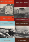
The Handy Series published in the 1980s by Milepost Publications

1 issue for each of the 5 regions , i seem to have about 3 or 4 different issues per region , give me a week or two and i will get them all up on my site - Transport Past Times
 

Attachments

  • Scan_20240830 (38).png
    Scan_20240830 (38).png
    425.8 KB · Views: 10

Andy873

Established Member
Joined
23 Mar 2017
Messages
1,411
It is a pretty useful railway measurement for mental assessing, as one chain was exactly the length of a standard Mk1/2 coach. So 10 chains is 10 coaches length.

Handy indeed! Now I can now visualise the length of a chain.
Yes, that's a easier way to visualise a chain.

The only feasible alternative route from Great Harwood to Padiham would have involved crossing the deep valley of the Hynd Burn somewhere around the road bridge. You would then have to cross the Calder somewhere between Altham and Padiham, so two smaller viaducts but a steeper gradient westbound through Gt H.
To me it looks as if the line took the most economical route overall, despite not being the shortest possible.


(OT, but the L and L Canal follows the contours spectacularly just to the south!)
Well, I've been looking at the OS 1894 hills map, with regards to this line's actual path. It does look like this was the only or most practical route available given the alternative gradients required.

The Leeds & Liverpool canal was of course built before the railway line and partially used up parts of land that if it hadn't been there the L&Y would have used it themselves.

I've been told the L&Y whenever practical followed the route of a canal closely, and other rail companies probably did the same trying to avoid those tougher gradients?
 

Taunton

Veteran Member
Joined
1 Aug 2013
Messages
12,256
Yes, that's a easier way to visualise a chain.


Well, I've been looking at the OS 1894 hills map, with regards to this line's actual path. It does look like this was the only or most practical route available given the alternative gradients required.

The Leeds & Liverpool canal was of course built before the railway line and partially used up parts of land that if it hadn't been there the L&Y would have used it themselves.

I've been told the L&Y whenever practical followed the route of a canal closely, and other rail companies probably did the same trying to avoid those tougher gradients?
Did they buy up the canal? A number of railway companies did, for the alignment, and in some cases (such as the GWR buying the Bridgwater & Taunton canal) for the water supply. Once the railway came along canals lost most of their trade, so were a cheap purchase.
 

edwin_m

Veteran Member
Joined
21 Apr 2013
Messages
28,637
Location
Nottingham
Yes, that's a easier way to visualise a chain.


Well, I've been looking at the OS 1894 hills map, with regards to this line's actual path. It does look like this was the only or most practical route available given the alternative gradients required.

The Leeds & Liverpool canal was of course built before the railway line and partially used up parts of land that if it hadn't been there the L&Y would have used it themselves.

I've been told the L&Y whenever practical followed the route of a canal closely, and other rail companies probably did the same trying to avoid those tougher gradients?
Probably not a matter of the railway builders choosing to follow the canal, more that both canals and railways were built to take advantage of the natural features of the land to minimise gradients, structures and earthworks. So in a lot of ways they were asking the same question and getting the same answer.

There are a couple of exceptions to this. Firstly tight curves aren't significant for a canal but are bad news for a railway. Secondly canals can climb very steep gradients if they have to, by means of chains of locks, but railways can only do so with cable haulage, which was recognised to be a bad idea for main lines very early in the railway age, or with racks which have never been widespread. These factors mean the railway will probably have more heavy engineering than a canal following a simlar route.
 
Status
Not open for further replies.

Top