• Our new ticketing site is now live! Using either this or the original site (both powered by TrainSplit) helps support the running of the forum with every ticket purchase! Find out more and ask any questions/give us feedback in this thread!

Autotransformer feeds

Status
Not open for further replies.

Barn

Established Member
Joined
3 Sep 2008
Messages
1,487
While staring out of the window this afternoon on the southern part of the MML, one thing was bugging me.

How come the contact cable in the OHLE (which I think is at 25kV) has big ceramic insulators when the autotransformer feeds (which I thought ran at 50kV) were apparently only centimetres away from the metal pillar on weedy litlle insulators?

Have I misunderstood the voltages and how the system works?
 
Sponsor Post - registered members do not see these adverts; click here to register, or click here to log in
R

RailUK Forums

Joseph_Locke

Established Member
Joined
14 Apr 2012
Messages
1,878
Location
Within earshot of trains passing the one and half
While staring out of the window this afternoon on the southern part of the MML, one thing was bugging me.

How come the contact cable in the OHLE (which I think is at 25kV) has big ceramic insulators when the autotransformer feeds (which I thought ran at 50kV) were apparently only centimetres away from the metal pillar on weedy litlle insulators?

Have I misunderstood the voltages and how the system works?


The southern MML is still on the original BT (booster transformer) system, so the cable on "weedy insulators" is the traction return cable, which shouldn't (normally) be many volts away from ground. BTs are the big things very few km, hung on the OLE structures.

The full AT system has a "negative" 25kV line on virtually full-size insulators, making a 50kVAC difference across contact and return lines.
 

TGV

Member
Joined
25 Nov 2005
Messages
734
Location
320km/h Voie Libre
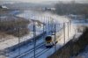
An autotransformer catenary system looks like the attached image.

Note the wires on the outside of the masts - they will look different to what you saw on a normal BR 25kV system.
 

Attachments

  • Eurostar-snow-pic resize.jpg
    Eurostar-snow-pic resize.jpg
    598.1 KB · Views: 117

Bald Rick

Veteran Member
Joined
28 Sep 2010
Messages
35,583
I'm pretty sure that the AT feed has been commissioned south of Borehamwood. Hence all the cash spent on new insulators and protection arrangements.
 

Edvid

Established Member
Joined
7 Feb 2008
Messages
2,472
That's right - during Christmas 2010, an AT system was commissioned between sites at Borehamwood and Kentish Town for about 20km; this includes a new feeder station and neutral section at Borehamwood.

Click here for an article on it.
 
Status
Not open for further replies.

Top