• Our new ticketing site is now live! Using either this or the original site (both powered by TrainSplit) helps support the running of the forum with every ticket purchase! Find out more and ask any questions/give us feedback in this thread!

Pros and cons of Continuous Welded Rail (CWR)

DelW

Established Member
Joined
15 Jan 2015
Messages
5,934
However, the extra cross-section means the force necessary to keep the rail at the correct length will be higher. The thicker section will be more resistant to buckling, but it's not clear to me which of these effects dominates.
It's a while since I've done these calcs in earnest, but I think:
  • The expansion or contraction force will be proportional to cross sectional area A as you say
  • The buckling failure load will be proportional to Moment of Inertia I (second moment of area) - from Euler's theory. Presumably the relevant value of I is about the weaker axis (used to be Iyy, though I think Eurocodes changed it to Izz).
Unfortunately calculating Iyy for a section like a rail isn't an easy task. But if the increased material in the cross section is added towards the extremes (away from the neutral axis), then the improved buckling resistance will likely outweigh the increased force. The effect will vary between different cross section geometries.

However, rail tracks are laterally restrained by fixings, sleepers and ballast, so Euler's values may not be directly applicable. I suspect that there are rules of thumb (or good practice) which are used, rather than engineering theory.
 
Sponsor Post - registered members do not see these adverts; click here to register, or click here to log in
R

RailUK Forums

Bryson

Member
Joined
24 Jan 2022
Messages
118
Location
Yorkshire
  • The buckling failure load will be proportional to Moment of Inertia I (second moment of area) - from Euler's theory. Presumably the relevant value of I is about the weaker axis (used to be Iyy, though I think Eurocodes changed it to Izz).
Unfortunately calculating Iyy for a section like a rail isn't an easy task. But if the increased material in the cross section is added towards the extremes (away from the neutral axis), then the improved buckling resistance will likely outweigh the increased force. The effect will vary between different cross section geometries.
From British Steel's data sheets:

1787069579803.png
 

trebor79

Established Member
Joined
8 Mar 2018
Messages
4,884
Yes I agree, but if you double the cross-section you need twice as much force to create the same stress and therefore to restrain the rail.
Perhaps, but we were talking about buckling in hot weather. If the rail is stressed to the same value it makes no odds.
Unfortunately calculating Iyy for a section like a rail isn't an easy task.
Indeed. I was exceedingly poor at calculating it even for simple sections.
 

edwin_m

Veteran Member
Joined
21 Apr 2013
Messages
28,586
Location
Nottingham
Perhaps, but we were talking about buckling in hot weather. If the rail is stressed to the same value it makes no odds.
I think that was my point, apologies if we're at cross purposes. If the rail is increased in every dimension so its shape remains the same, then in itself it will be equally likely to buckle for the same rise in temperature assuming the temperature persists long enough for conduction to equalise it across the rail section.

However, a heavier rail section introduces larger forces, so may require more effective restraints (fasteners, sleepers and ballast).
 

AirGamer

Member
Joined
18 Jan 2022
Messages
5
Location
Hull
I think that was my point, apologies if we're at cross purposes. If the rail is increased in every dimension so its shape remains the same, then in itself it will be equally likely to buckle for the same rise in temperature assuming the temperature

I believe simply scaling up the cross-section would still give greater resistance, as the moment of inertia would increase faster than the cross-sectional area (and thus force from thermal induced stress).
 

Annetts key

Established Member
Joined
13 Feb 2021
Messages
3,787
Location
West is best
A chart showing rail details was posted in post #62.

On the area where I worked, most rail was BS 113. But various renewals replaced lengths (of various distances) with RT60 / UIC 60. UIC 60 being the current preferred standard for planned track renewals on most main lines (as I understand it).

Where the UIC 60 met with the existing BS 113, transition rails are used. Both ends of these are welded to the adjacent rails.

I can't remember much UIC 54 being used apart from various points.

Anyways, that chart does give the moment of inertia for each rail profile / type

As you can see, UIC 60, being heavier does have a larger moment of inertia.
 

trebor79

Established Member
Joined
8 Mar 2018
Messages
4,884
I think that was my point, apologies if we're at cross purposes. If the rail is increased in every dimension so its shape remains the same, then in itself it will be equally likely to buckle for the same rise in temperature assuming the temperature persists long enough for conduction to equalise it across the rail section..
No.
I believe simply scaling up the cross-section would still give greater resistance, as the moment of inertia would increase faster than the cross-sectional area (and thus force from thermal induced stress).
Correct.

Is it easier to buckle a thing section or a thick section, The thin section obviously. The buckling force applied is determined by the longitudinal expansion, which is the same at a given temperature for both thin and thick sections..
 

andy33gmail

Member
Joined
23 Mar 2025
Messages
291
Location
cambridgeshire
At the risk of being called out as an "alleged metallurgist"

Could you use dovetail joints; have an overlapping section where there's enough structure, the correct top profile, put the two sections can vary how much they overlap?

With of course guard rails, appropriate inspections, maybe some additional structure to ensure no lateral movement
 

Annetts key

Established Member
Joined
13 Feb 2021
Messages
3,787
Location
West is best
At the risk of being called out as an "alleged metallurgist"

Could you use dovetail joints; have an overlapping section where there's enough structure, the correct top profile, put the two sections can vary how much they overlap?

With of course guard rails, appropriate inspections, maybe some additional structure to ensure no lateral movement
That's essentially what a rail expansion joint, also known as breather switch is. Details in this Wikipedia article.
 

edwin_m

Veteran Member
Joined
21 Apr 2013
Messages
28,586
Location
Nottingham
No.

Correct.

Is it easier to buckle a thing section or a thick section, The thin section obviously. The buckling force applied is determined by the longitudinal expansion, which is the same at a given temperature for both thin and thick sections..
I believe simply scaling up the cross-section would still give greater resistance, as the moment of inertia would increase faster than the cross-sectional area (and thus force from thermal induced stress).
The amount of force compressing the rail depends on the cross-sectional area. The amount the shape resists bending depends on the moment of inertia. Assuming the cross-section shape remains the same (similar in mathematical terms), both of these vary as the square of a linear dimension.
 

ac6000cw

Established Member
Joined
10 May 2014
Messages
3,884
Location
Cambridge, UK
When the forces within the rails get too high for the fastenings/sleepers/ballast to resist, is it more common for the whole track structure (rails and sleepers as a unit) to move/bend/buckle or for just one rail to break free of the fastenings (or fastenings break free from the sleepers)?

(I think most pictures I've seen over the years of track buckles show the whole track structure having distorted i.e. the restraint from ballast has given way)
 

Bald Rick

Veteran Member
Joined
28 Sep 2010
Messages
35,581
When the forces within the rails get too high for the fastenings/sleepers/ballast to resist, is it more common for the whole track structure (rails and sleepers as a unit) to move/bend/buckle or for just one rail to break free of the fastenings (or fastenings break free from the sleepers)?

(I think most pictures I've seen over the years of track buckles show the whole track structure having distorted i.e. the restraint from ballast has given way)

The whole lot, unless there is something unusual, eg different SFTs in the two rails (not unheard of).
 
Last edited:

Annetts key

Established Member
Joined
13 Feb 2021
Messages
3,787
Location
West is best
When the forces within the rails get too high for the fastenings/sleepers/ballast to resist, is it more common for the whole track structure (rails and sleepers as a unit) to move/bend/buckle or for just one rail to break free of the fastenings (or fastenings break free from the sleepers)?

(I think most pictures I've seen over the years of track buckles show the whole track structure having distorted i.e. the restraint from ballast has given way)
On the few occasions when I've seen it, the forces caused both rails to bend and in doing so, the sleepers moved sideways a little. I don't remember any broken fastenings / fixings (rail clips).

Unless it's near S&C. With points it's more common for the switch rail to no longer line up correctly with the "fixed" stock rail. The switch rail either creeps forward or moves in the opposite direction compared to the stock rail. This movement, if excessive will eventually cause the point operating equipment to be unable to operate the points correctly. Or if it's the other rail (or both rails) the rails for the turn out may go out of alignment. Again, I don't remember seeing any broken fixings.
 

AirGamer

Member
Joined
18 Jan 2022
Messages
5
Location
Hull
The amount of force compressing the rail depends on the cross-sectional area. The amount the shape resists bending depends on the moment of inertia. Assuming the cross-section shape remains the same (similar in mathematical terms), both of these vary as the square of a linear dimension.

Simplifying down to a rectangular profile of 10x5cm
The cross sectional area would be 10x5 = 50cm2
The second moment of area for a rectangle would be (BxD^3) / 12 for the major axis, or (DxB^3) / 12 for the minor axis.
Along the weaker minor axis, the second moment of area would be (10x5^3) / 12 = 104.2cm4.

For a section 2x as large (20x10cm)
The cross sectional area would be 20x1 = 200cm2 (4x)
The second moment of area, along the weaker axis would be (20x10^3) / 12 = 1666.7cm4 (16x)

While rails are a significantly more complex profile, I would expect the general trend to hold true.
 

trebor79

Established Member
Joined
8 Mar 2018
Messages
4,884
The amount of force compressing the rail depends on the cross-sectional area.
No, it does not. The compressive force comes from longitudinal expansion and that is the same regardless of cross-sectional area.
 

edwin_m

Veteran Member
Joined
21 Apr 2013
Messages
28,586
Location
Nottingham
No, it does not. The compressive force comes from longitudinal expansion and that is the same regardless of cross-sectional area.
The stress is the same, but stress is force divided by cross-sectional area. So with the same stress (which you've agreed in earlier posts) a larger cross-section will need more force to prevent expansion.
 

sikejsudjek

Member
Joined
7 Aug 2018
Messages
30
Lots more maintenence with jointed track. Dipped joints, bent rail ends, broken and cracked fishplates, rail gaps need checking as rail can creep and close gaps on enough 60ft sections to buckle rails, fishplates need greasing or can rust to rails and cause buckles.
 

njamescouk

Member
Joined
8 Apr 2017
Messages
201
The stress is the same, but stress is force divided by cross-sectional area. So with the same stress (which you've agreed in earlier posts) a larger cross-section will need more force to prevent expansion.
fwiw my memory of A level physics from 50 years ago:

1. extend a sample by a certain distance, which will require a force dependent on material, x-section etc etc.

2. extend the same sample by the same distance by heating it.

3. the force needed to restrain the expansion in example 2 is equal to the force employed in example 1.

alternatively 4. the force exterted by the expansion in example 2 is equal to the force employed in example 1.

stress something something youngs modulus strain can't remember what's what now.

no doubt the real world is more complicated...
 

RGM654

Member
Joined
19 Jul 2022
Messages
242
Location
Harrow
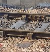
This is not concerned with the main theme here of how to avoid buckling in hot weather and cracking in cold weather, but I think it is close enough to the thread subject to go here rather than in a new thread. (If not, mods please move.) I recently noticed an unsual rail joint on one of the platform roads at York: one side welded and the other fishplated. Why might that be?
 

Attachments

  • Rail joint.jpg
    Rail joint.jpg
    367.9 KB · Views: 64

Annetts key

Established Member
Joined
13 Feb 2021
Messages
3,787
Location
West is best
This is not concerned with the main theme here of how to avoid buckling in hot weather and cracking in cold weather, but I think it is close enough to the thread subject to go here rather than in a new thread. (If not, mods please move.) I recently noticed an unsual rail joint on one of the platform roads at York: one side welded and the other fishplated. Why might that be?

In this particular case, the fishplated joint looks like it's an IRJ (Insulated Rail Joint) used to separate two different track circuits. Because there is an IRJ in one rail only, it must be a "single rail" track circuit area (although the track circuit does actually use both rails, the "single rail" referring to IRJs only being installed in one rail, as opposed to "double rail" track circuits which have IRJs installed in both rails).

But occasionally even where there aren't IRJs, you may find differences due to other reasons. Maybe there had been a rail defect at some time in the past.

If you look at the welded joint, there are no bolt holes where a fishplated joint would have been. So it was intended to weld together the two rails.
 
Last edited:

Bald Rick

Veteran Member
Joined
28 Sep 2010
Messages
35,581
Yep definitely an IBJ, as those bolts can‘t be tightened, and there’s no gap.
 

BRX

Established Member
Joined
20 Oct 2008
Messages
4,477
The whole lot, unless there is something unusual, eg different SFTs in the two rails (not unheard of).
Does this mean that track on concrete slab is much less likely to buckle? Or does the point of failure just transfer to the rail fixings instead.
 

Bald Rick

Veteran Member
Joined
28 Sep 2010
Messages
35,581
Does this mean that track on concrete slab is much less likely to buckle?

Correct. I’ve never known slab track buckle in this country. Albeit a high proportion of slab track in this country is in tunnels, where rail temperature isn’t an issue (and rails are typically not stressed)
 

Top