• Our new ticketing site is now live! Using either this or the original site (both powered by TrainSplit) helps support the running of the forum with every ticket purchase! Find out more and ask any questions/give us feedback in this thread!

Historical Track Circuit Questions

Status
Not open for further replies.

Andy873

Established Member
Joined
23 Mar 2017
Messages
1,415
At two stations of interest to me track circuits were installed. One in 1914, and two more at a second station in 1925.

They seem to have been installed when signalling was moved out of sight of the corresponding signal boxes, which of course makes sense. These stations were L&Y and later LMS ones.

I know very little about these older track circuits so could someone please explain:

Was 1914 early for a track circuit or were they quite common by then?
I'm presuming there would be some sort of indicator in the box to tell the signaller the circuit was occupied by a train or not?

Would this indicator be a device with a pointer stating something like train in section or normal? or would there be some sort of light that lit up when the circuit was occupied? and when the state of the circuit changed, was there an audible sound such as a bell?
 
Sponsor Post - registered members do not see these adverts; click here to register, or click here to log in
R

RailUK Forums

Gloster

Veteran Member
Joined
4 Sep 2020
Messages
13,017
Location
Up the creek
Regarding what they looked like: there is a video from the National Railway Museum from 2012 called Lancashire and Yorkshire School of Signalling. It lasts 5.30, but at 2.01 you get a brief glimpse of a track circuit indicator down in the bottom right corner: it is a round case about 2” deep and 4” across with a red transversal bar at the front of the case, just behind the glass. That is, if I remember, track unoccupied when horizontal: if the track is occupied the bar goes to a north-east to south-west position. One point of caution: it is possible that this is a later LMS or BR type that has replaced the original. There were various types and I can’t be certain that this is the same or similar to an L&Y one. (Those I used on the Southern and Western Region were different.) It could also be in this instance a signal indicator, but similar mountings were used for the two functions.

There was no audible sound in most cases, just a clunk or a faint click that only a signalman would hear. Sometimes it would be considered necessary to alert a signalman that a train had reached a certain point: at one box we had a ‘dying duck’.
 

Railsigns

Established Member
Joined
15 Feb 2010
Messages
2,754
it is a round case about 2” deep and 4” across with a red transversal bar at the front of the case, just behind the glass. That is, if I remember, track unoccupied when horizontal: if the track is occupied the bar goes to a north-east to south-west position.
The banner was horizontal for occupied and inclined for clear. The ones I've seen had a black banner, like the standard BR indicator illustrated below:

TC ind.jpg
 

John Webb

Established Member
Joined
5 Jun 2010
Messages
3,779
Location
St Albans
The banner was horizontal for occupied and inclined for clear. The ones I've seen had a black banner, like the standard BR indicator illustrated below:

View attachment 162933
Possibly worth a mention that unpowered it would be horizontal indicating 'Track Occupied' and was powered to the 'Track Clear' position so that if the indicator failed or its power failed it would 'fail-safe' to show occupied?
 

Gloster

Veteran Member
Joined
4 Sep 2020
Messages
13,017
Location
Up the creek
I have to say that the SR and WR boxes I worked in had illuminated diagrams, so no TC indicators, and the signal repeaters were of the type with an arrow. The arrow pointed to the left for Signal On, to the right for Signal Off and straight down for defective.
 

DerekC

Established Member
Joined
26 Oct 2015
Messages
2,439
Location
Hampshire (nearly a Hog)
As regards the date - the fail safe DC track circuit was invented and patented in the USA in 1872 by Dr William Robinson, although a non-fail-safe version had been demonstrated earlier in the UK. As far as I can find out the first use in the UK was in 1894 at Kings Cross for traffic through Gasworks Tunnel. AC track circuits were first used in the UK in 1903 on the Metropolitan District Railway.
 

Rescars

Established Member
Joined
25 May 2021
Messages
2,560
Location
Surrey
IIRC the BoT first recommended the installation of track crcuits following the accident at Thirsk in 1892.
 

Andy873

Established Member
Joined
23 Mar 2017
Messages
1,415
Thanks all for explaining how it was put into practice. I guess then, by 1914 they were becoming more and more popular.

It clearly added an extra level of safety in certain locations plus it also meant that some signals could be moved further away from a signal box, sometime out of sight of the box itself.
 

Rescars

Established Member
Joined
25 May 2021
Messages
2,560
Location
Surrey
By 1914, more commonplace in more challenging locations, but by no means universal. There were no track circuits at Quintinshill in May 1915.
 

edwin_m

Veteran Member
Joined
21 Apr 2013
Messages
28,691
Location
Nottingham
By 1914, more commonplace in more challenging locations, but by no means universal. There were no track circuits at Quintinshill in May 1915.
I think there was a presumption that they weren't necessary close to the box where the signalman could easily see whether a train was present. But Quintinshill is one of a series of bad accidents where such a train was forgotten anyway.
 

John Webb

Established Member
Joined
5 Jun 2010
Messages
3,779
Location
St Albans
The Midland Railway accident at Ais Gill on Christmas Eve, 1910, where the Hawes Junction (now Garsdale) signalman forgot he had two light engines standing on the main line ready to return to Carlisle and cleared the line for an express train which caught up with the slower-moving light engines with fatal consequences. The engines had not been visible on a dark and wet evening. Subsequently the MR identified 2,000 locations where track circuits should be installed. St Albans got its track circuits in late 1915.
 

Andy873

Established Member
Joined
23 Mar 2017
Messages
1,415
IIRC the BoT first recommended the installation of track crcuits following the accident at Thirsk in 1892.
The Midland Railway accident at Ais Gill on Christmas Eve, 1910, where the Hawes Junction (now Garsdale) signalman forgot he had two light engines standing on the main line ready to return to Carlisle and cleared the line for an express train which caught up with the slower-moving light engines with fatal consequences. The engines had not been visible on a dark and wet evening. Subsequently the MR identified 2,000 locations where track circuits should be installed. St Albans got its track circuits in late 1915.
So it seems that in the late 19th century these circuits were being recommended. Glad to see St. Albans got its circuit shortly after the first of the stations on my old branch got theirs.

Question: How were these circuits isolated from adjoining sections of track? traditionally fish plates (made of metal) would join the end of one track to the start of the next one, would that not cause some sort of circuit leak?
 

John Webb

Established Member
Joined
5 Jun 2010
Messages
3,779
Location
St Albans
So it seems that in the late 19th century these circuits were being recommended. Glad to see St. Albans got its circuit shortly after the first of the stations on my old branch got theirs.

Question: How were these circuits isolated from adjoining sections of track? traditionally fish plates (made of metal) would join the end of one track to the start of the next one, would that not cause some sort of circuit leak?
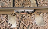
I don't have any photos to hand, but Insulated Rail Joints were made by having a fibre (Tuffnol?) section inserted between the rail ends, similar insulation between the rails and the metal fishplates and insulating tubes through the bolt holes in the rails to ensure bolts clamping everything together didn't come into contact with the rails.
 

Rescars

Established Member
Joined
25 May 2021
Messages
2,560
Location
Surrey
I may be imagining this, but were there such things as wooden fishplates to achieve TC insulation?
 

John Webb

Established Member
Joined
5 Jun 2010
Messages
3,779
Location
St Albans
I may be imagining this, but were there such things as wooden fishplates to achieve TC insulation?
They may have used wood as the insulating medium but I've never come across a reference in any of my books to wood only as a means of securing rail joints. The insulating material I referred to in my previous post was developed in the very early C20 for use in wireless telegraphy and the like.
 

Railsigns

Established Member
Joined
15 Feb 2010
Messages
2,754
Here's a photo of an insulated rail joint. This one has four holes, but some have six.

== Doublepost prevention - post automatically merged: ==

I may be imagining this, but were there such things as wooden fishplates to achieve TC insulation?
Permali is a manufacturer of densified wood fishplates.
 

Attachments

  • IRJ 4 hole.jpg
    IRJ 4 hole.jpg
    212.8 KB · Views: 16
Last edited:

AndrewE

Established Member
Joined
9 Nov 2015
Messages
7,350
Wasn't the main aim of some early track circuits (before track-circuit block) to lock points when there was a train approaching them, preventing them being moved under the train?
 

matchmaker

Established Member
Joined
8 Mar 2009
Messages
1,883
Location
Central Scotland
The Midland Railway accident at Ais Gill on Christmas Eve, 1910, where the Hawes Junction (now Garsdale) signalman forgot he had two light engines standing on the main line ready to return to Carlisle and cleared the line for an express train which caught up with the slower-moving light engines with fatal consequences. The engines had not been visible on a dark and wet evening. Subsequently the MR identified 2,000 locations where track circuits should be installed. St Albans got its track circuits in late 1915.
Midland Railway track circuit no. 1 was installed at Mansfield, although I don't know the date. Historical trivia - the white diamond signal post plate denoting a track circuit and still in use to this day was designed by W.C. Acfield of the Midland Railway in 1915.
 

Gloster

Veteran Member
Joined
4 Sep 2020
Messages
13,017
Location
Up the creek
Midland Railway track circuit no. 1 was installed at Mansfield, although I don't know the date. Historical trivia - the white diamond signal post plate denoting a track circuit and still in use to this day was designed by W.C. Acfield of the Midland Railway in 1915.

Midland Railway Track Circuit No. 1 was installed (‘was commenced’) on December 16th 1906, although the paperwork didn’t catch up and that says June 17th 1909. The Midland was somewhat late in adopting T.C.s as it was sceptical about their reliability.

Source: The Signalling Record, No. 209.
 

D7666

Member
Joined
12 Aug 2013
Messages
998
Historically getting fail-safe track circuits to detect right took time, and is /one/ reason for lag between invention and implementation (although resisting doing it at all was significant).

DEV dual element vane relays were the real big jump - never mind your signal box indicator or lamp in a diagram or what the TC was used to do, they all need calibrated relays to fail-safe operate, none of it is an use without the relay.

DEV despite the Edwardian technology are still used in many locations especially inconjunction at traditional mechanical interlocking sites; they are sometimes known as 'fishtank' relays.

example reading :

LU article yes but such relays are equally found on main line

BR 906 (is that the right code?) a.k.a. Q relays are the later 20C equivalent.
 

jmh59

Member
Joined
7 May 2018
Messages
154
Location
Leeds
DEV dual element vane relays were the real big jump - never mind your signal box indicator or lamp in a diagram or what the TC was used to do, they all need calibrated relays to fail-safe operate, none of it is an use without the relay.

DEV despite the Edwardian technology are still used in many locations especially inconjunction at traditional mechanical interlocking sites; they are sometimes known as 'fishtank' relays.
Those were for AC track circuits weren't they? DC is a lot simpler. Aster comes to mind too but way more complex than our heritage stuff, battery at one end and relay at the other.
 

D7666

Member
Joined
12 Aug 2013
Messages
998
Those were for AC track circuits weren't they? DC is a lot simpler. Aster comes to mind too but way more complex than our heritage stuff, battery at one end and relay at the other.
On DC electrified railways you do tend to have AC track circuits.
 

jmh59

Member
Joined
7 May 2018
Messages
154
Location
Leeds
On DC electrified railways you do tend to have AC track circuits.
Ah yes makes perfect sense - thanks. This is the older type of TC relay we have.
 

Attachments

  • IMG_8814.jpeg
    IMG_8814.jpeg
    68.6 KB · Views: 14
Status
Not open for further replies.

Top