I wondered that. The end of the bridge spans - the place where the bearings are - does not seem to be immediately above the line of piles. Therefore there is a short cantilever of some sort from centre of pile to centre of bearing, where all the live and dead loads act.

-
Our new ticketing site is now live! Using either this or the original site (both powered by TrainSplit) helps support the running of the forum with every ticket purchase! Find out more and ask any questions/give us feedback in this thread!
You are using an out of date browser. It may not display this or other websites correctly.
You should upgrade or use an alternative browser.
You should upgrade or use an alternative browser.
Nuneham Viaduct shut - Didcot- Oxford
- Thread starter deltic
- Start date
- Status
- Not open for further replies.
Sponsor Post - registered members do not see these adverts; click here to register, or click here to log in
R
RailUK Forums
I may be missing something, but the picture in https://www.railforums.co.uk/threads/nuneham-viaduct-shut-didcot-oxford.246310/post-6234536 appears to show the end of the bridge being above the line of piles.I wondered that. The end of the bridge spans - the place where the bearings are - does not seem to be immediately above the line of piles. Therefore there is a short cantilever of some sort from centre of pile to centre of bearing, where all the live and dead loads act.

reddragon
Established Member
There was a 500mm steel bolted water main on the bridge and it had bent under spring loadings by 600mm. The stored energy in that was massive & cutting it was lets say was a bit exciting!

Fortunately, the water main had already been diverted because of the ongoing movement, otherwise just starting the job could have been delayed by a few weeks!
Fortunately, the water main had already been diverted because of the ongoing movement, otherwise just starting the job could have been delayed by a few weeks!
edwin_m
Veteran Member
Looking at earlier images, they have taken out the end part of the steel deck that supports the track, to make room for the piles and the piling rig to go through this area. However, they can't cut the ends off the main girders in this way, at least not if they intend to restore them, so no piles can go directly under those girders. The cill beam will sit on the piles and transfer the load downward and sideways into the piles from the girders which will sit on it, probably with some sort of bearing to account for expansion. Thus the cill beam will have some bending load but nowhere near as much as that of the girders themselves (since bending load depends on the distance away where the force acts, multiplied by the size of the force).
Oxfordblues
Member
- Joined
- 22 Dec 2013
- Messages
- 1,127
I'd like to say that Stuart Calvert has emerged as a star engineer in Network Rail videos with his knowledgeable, enthusiastic and optimistic presentations. He comes across as a "Fred Bibnah of our age"!

Elecman
Established Member
Fred DibnahI'd like to say that Stuart Calvert has emerged as a star engineer in Network Rail videos with his knowledgeable, enthusiastic and optimistic presentations. He comes across as a "Fred Bibnah of our age"!
Yes it does.
I may be missing something, but the picture in https://www.railforums.co.uk/threads/nuneham-viaduct-shut-didcot-oxford.246310/post-6234536 appears to show the end of the bridge being above the line of piles.
Snow1964
Established Member
The photo also shows what looks like a black circular template, sitting on the scaffold boards between the piles. The holes are small but look to be in same position as those galvanised caps.That's an unusual pile cap detail - I've seen quite a few pile caps and piled abutments and I've never seen one that looked anything like that. The shear design would be interesting, I'm guessing it must be done according to the steel rather than concrete code to use those bolted connections. Innovative design by someone! The holes in the capping plates suggest that the piles may be filled with concrete before or possibly during the abutment pour.
There have certainly been some unusual challenges and solutions on this job, it's kept me guessing throughout. I hope someone involved will produce a technical paper explaining it all once the metaphorical dust has settled
I'n guessing it is placed over the piles and small Pilot holes are drilled, or at least started, so the big drill for the bolts doesn't skid around on side of piles

DelW
Established Member
- Joined
- 15 Jan 2015
- Messages
- 6,018
It does indeed look like a template.The photo also shows what looks like a black circular template, sitting on the scaffold boards between the piles. The holes are small but look to be in same position as those galvanised caps.
I'n guessing it is placed over the piles and small Pilot holes are drilled, or at least started, so the big drill for the bolts doesn't skid around on side of piles
I've been automatically assuming concrete filled piles and a concrete abutment, but this detail is suggesting maybe the whole thing will be done in structural steelwork? That would be a bit unconventional but it would allow more prefabrication and avoids curing time.
I'd like to say that Stuart Calvert has emerged as a star engineer in Network Rail videos with his knowledgeable, enthusiastic and optimistic presentations. He comes across as a "Fred Bibnah of our age"!
I’ll tell him that. Not sure he’ll take it as a compliment.
Snow1964
Established Member
It does indeed look like a template.
I've been automatically assuming concrete filled piles and a concrete abutment, but this detail is suggesting maybe the whole thing will be done in structural steelwork? That would be a bit unconventional but it would allow more prefabrication and avoids curing time.
Possibly will be a steel beam which bridge is then lowered onto.
I would not be surprised if all those steel piles are then enclosed in a concrete box to create an abutment for the end of the embankment.
My guess is possibly will initially drive pile wall (zigzag style piles) to support end of embankment, then subsequently backfill around the piles with concrete after line is reopened to form permanent abutment. I would guess aim is to get line open by 10th (with speed restriction) even if work then needs to be finished to complete it and lift speed restriction afterwards.
Looks like the chalked ovals on the 2 nearest tubular piles are highlighting 'pop' marks for drilling the holes for the bolts (HSFG* ?) to fix the caps on those piles, then a big (upwards of 1 metre deep) traverse header beam across the 8 piles to support bearings for the ends of the 3 main girders.
Not clear at this time what the plans are for filling between the piles for the embankment reinstatement beyond the new abutment.
* HSFG= High Strength Friction Grip bolts, these rely on bolts strong enough to hold the 2 parts by friction between them, rather than fitted bolts which require precision fitting a bit like rivets would achieve.
Not clear at this time what the plans are for filling between the piles for the embankment reinstatement beyond the new abutment.
* HSFG= High Strength Friction Grip bolts, these rely on bolts strong enough to hold the 2 parts by friction between them, rather than fitted bolts which require precision fitting a bit like rivets would achieve.
Hellzapoppin
Member
- Joined
- 16 Jan 2016
- Messages
- 267
Just don't mention Gypsy Patch bridge.I’ll tell him that. Not sure he’ll take it as a compliment.
Just don't mention Gypsy Patch bridge.
yes that was a ‘fun’ conversation.
Just had to google it - a delayed project and the transporter got stuck in the mud!Just don't mention Gypsy Patch bridge.
https://en.wikipedia.org/wiki/Gipsy_Patch_Lane_Bridge

D6130
Established Member
The late Fred Dibnah had quite a strong command of the English language....but with a very strong Bolton accent!I always thought Fred Dibnah had limited command of the English language.

Dunfanaghy Rd
Member
Interesting, and amusing, as long as he stuck to the day job - bringing down chimneys. As an instant expert on railways and steam machinery he was a country mile outside his comfort zone!The late Fred Dibnah had quite a strong command of the English language....but with a very strong Bolton accent!
Pat
-Colly405-
Member
What Google doesn't say is that once the road re-opened, there were then issues with the new embankment, so the junction with Station Road and also one lane of GPL itself were closed again, with it *finally* reopening in full just a week or two ago.Just had to google it - a delayed project and the transporter got stuck in the mud!
https://en.wikipedia.org/wiki/Gipsy_Patch_Lane_Bridge
http://www.stokegiffordjournal.co.uk/2023/03/30/station-road-reopening-delayed-for-the-fourth-time/
gives more detail...
Oh dear, worst than I realised - I bet you are all fed up with the works.What Google doesn't say is that once the road re-opened, there were then issues with the new embankment, so the junction with Station Road and also one lane of GPL itself were closed again, with it *finally* reopening in full just a week or two ago.
http://www.stokegiffordjournal.co.uk/2023/03/30/station-road-reopening-delayed-for-the-fourth-time/
gives more detail...
Also ask him if they can cut the music from his videos, no need for it!I’ll tell him that. Not sure he’ll take it as a compliment.
YES, yes yes! Agreed. It's at best irritating, at worst obscures points in the narative.Also ask him if they can cut the music from his videos, no need for it!
OneOfThe48
Member
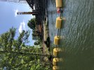
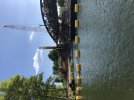
This ground definitely does not look load bearing!
stevewalls
New Member
I have come across piles driven into really poor ground, they were hollow steel tube with a flat shoe, driven to refusal. After installing a pre-assembled steel reinforcement cage, they were backfilled with concrete, and the tube vibrated out. That could what we are seeing here.It looks to me as though they're using both of the hydraulic leader rigs to vibrate in the casings as far as they'll go, then using what looks like a diesel hammer on the Weldex crawler to drive either to a set or to a level. If they need a high end bearing capacity, it may be easier to drive empty casing open-ended then auger it out rather than having to drive with a shoe meaning lots of ground displacement. I can't see what item of plant the auger would be mounted on, but maybe it can be fitted to one of the leader rigs.
I think in this location, unless relying on using a continuous flight auger and concreting via the auger stem, you'd want casing right through the alluvial ground. If they penetrate firm clay or similar then open bore might work over the deeper part. I imagine a reinforced concrete shaft will be needed for the required design life.
With a bit of luck NCE might do a full report before long.

Pete_uk
On Moderation
That's just crazy!This ground definitely does not look load bearing!
quantinghome
Established Member
- Joined
- 1 Jun 2013
- Messages
- 2,892
The tube in your example would have been a temporary casing. These are the permanent piles - they have structural attachments on the pile heads.I have come across piles driven into really poor ground, they were hollow steel tube with a flat shoe, driven to refusal. After installing a pre-assembled steel reinforcement cage, they were backfilled with concrete, and the tube vibrated out. That could what we are seeing here.
My experience of piling was different. The steel tubes, about 400mm diam, had a 'plug' of gravel dropped into them, coming to rest on a slightly coned steel lid, or hat, or foot, or base - it'll have a name, no doubt. Then each pile was craned to the vertical and suspended over the disignated spot, and a big weight dropped down the bore onto the gravel cushion at the bottom. Each drop pulled the tube down into the ground - 200mm per drop at first, gradually reducing drop by drop. The engineer in charge stopped the operation when sucessive drops yielded lesss than a pre-determined amount - about 5mm - that sort of thing. They were then burned off at the appropriate height, a pre-formed re-inforcement 'cage' slid down the bore, then filled with concrete. He had a vibrator attached to the reinforcement cage which ensured the penetration of the mix to the very bottom - where the gravel plug was. The builder then constructed formwork for the re-inforced concrete foundation beams which spanned pile-to-pile, so both the steel tube and it's concrete core both remained.
I don't think they did that here.
I don't think they did that here.
DelW
Established Member
- Joined
- 15 Jan 2015
- Messages
- 6,018
Looking at the recent photos, I'm thinking that maybe there will be two separate steel structures, possibly without concreting anything. The heavy section steel Z-piles seen in post #863 could work in cantilever to form the abutment wall, ballast wall and wing walls. Then a separate bearing shelf (more like a bearing beam in this case) could be fixed across the plates bolted to the heads of the tubular piles - those bolted connections are designed to carry a substantial loading on their own. That beam would support bearings for the truss ends of the decks.
There again most of my speculations have turned out to be wrong so far and they might be again . This looks like being quite an unconventional design.
Piles can be driven by drop hammer, air hammer, diesel hammer, vibrator or hydraulic ram, depending on ground conditions and the need to avoid effects on nearby buildings or people. The driver in post #863 and some earlier pictures looks like a diesel hammer to me - they're noisy but that's probably not an issue here. I'm unclear what the augers might have been used for, pre-boring doesn't seem to have been necessary in such soft ground. The diesel hammer would have been needed to achieve the required penetration or set in the firmer strata at toe level.
There again most of my speculations have turned out to be wrong so far and they might be again
. This looks like being quite an unconventional design.Piles can be driven by drop hammer, air hammer, diesel hammer, vibrator or hydraulic ram, depending on ground conditions and the need to avoid effects on nearby buildings or people. The driver in post #863 and some earlier pictures looks like a diesel hammer to me - they're noisy but that's probably not an issue here. I'm unclear what the augers might have been used for, pre-boring doesn't seem to have been necessary in such soft ground. The diesel hammer would have been needed to achieve the required penetration or set in the firmer strata at toe level.
Well, they (the great un-known "They") know what they've done and what they're gonna do, don't they?Looking at the recent photos, I'm thinking that maybe there will be two separate steel structures, possibly without concreting anything. The heavy section steel Z-piles seen in post #863 could work in cantilever to form the abutment wall, ballast wall and wing walls. Then a separate bearing shelf (more like a bearing beam in this case) could be fixed across the plates bolted to the heads of the tubular piles - those bolted connections are designed to carry a substantial loading on their own. That beam would support bearings for the truss ends of the decks.
There again most of my speculations have turned out to be wrong so far and they might be again
Piles can be driven by drop hammer, air hammer, diesel hammer, vibrator or hydraulic ram, depending on ground conditions and the need to avoid effects on nearby buildings or people. The driver in post #863 and some earlier pictures looks like a diesel hammer to me - they're noisy but that's probably not an issue here. I'm unclear what the augers might have been used for, pre-boring doesn't seem to have been necessary in such soft ground. The diesel hammer would have been needed to achieve the required penetration or set in the firmer strata at toe level.
'They' could post an explanation on here, then we wouldn't be guessing all the time. That'd be nice, but I suppose it would invite amateur criticism before the event which'd be a nuisance to 'them' I guess.
- Status
- Not open for further replies.