• Our new ticketing site is now live! Using either this or the original site (both powered by TrainSplit) helps support the running of the forum with every ticket purchase! Find out more and ask any questions/give us feedback in this thread!

Nuneham Viaduct shut - Didcot- Oxford

Status
Not open for further replies.

GRALISTAIR

Established Member
Joined
11 Apr 2012
Messages
10,520
Location
Preston Lancs
Heaven forbid that someone is just curious.
I have learned on this board not to take things too seriously. There are some very snippy remarks from time to time. This boards massive strengths far outweigh its weaknesses. A goldmine of information.
 
Sponsor Post - registered members do not see these adverts; click here to register, or click here to log in
R

RailUK Forums

Nicholas43

Member
Joined
16 Jun 2011
Messages
652
Location
Radley
The shuttle Radley - Oxford doesn't seem to be running this week. Real time trains shows it running 22 to 26 May, 3 trips morning, 3 trips afternoon, with times tweaked.
 

Jimini

Established Member
Joined
8 Oct 2006
Messages
2,165
Location
Reading
All on schedule so far…

Good to hear. Another journey for me on a via. Reading ticket to Paddington, H&C and then out of Euston today. Ticket acceptance still being ok'd in good grace at all points throughout the journey, I'm pleased to report.

My journey south on Monday (via. Brum and Cheltenham (fancied a change)) was scuppered by the XC service being 12 minutes late at Cheltenham due to being let out of New Street following a stopper to Bromsgrove, so missed the hourly connection at Cheltenham. Stayed on the XC train to Gloucester and changed there instead. Went for a quick pint at the 'Spoons in Gloucester. Now that's one hell of a people watching pub!! :lol:
 

Kingham West

Member
Joined
17 Oct 2017
Messages
132
This evening, work progressing
 

Attachments

  • E7A15837-C15E-4C8E-882E-E7A033A1D18F.jpeg
    E7A15837-C15E-4C8E-882E-E7A033A1D18F.jpeg
    2.8 MB · Views: 331
  • 173DDB41-4AFC-4970-BF7D-01ABD9B4095F.jpeg
    173DDB41-4AFC-4970-BF7D-01ABD9B4095F.jpeg
    4.1 MB · Views: 327

quantinghome

Established Member
Joined
1 Jun 2013
Messages
2,893
Latest tweet from NR Western:

Looks like they are driving steel piles to firm strata and then presumably augering out the fill and pouring concrete into them.
It depends on the ground and the pile design. The capacity comes from a combination of friction down the pile plus end bearing at the bottom. The piles may have been designed to rely purely on friction (particularly if firm strata is very deep), in which case concrete fill wouldn't be needed. Or the material inside the pile could be secure enough to plug the pile end, in which case you get the end bearing support without replacing it with concrete.
 

DelW

Established Member
Joined
15 Jan 2015
Messages
6,021
Latest tweet from NR Western:

Looks like they are driving steel piles to firm strata and then presumably augering out the fill and pouring concrete into them.
One of the overhead pictures in that link answers a question I posed earlier:
I'm curious to see how the abutment piles will be installed below the deck, even when it's been jacked back up to level. Or possibly they will be installed as two groups, one either side of the deck, with the abutment wall as a deep beam spanning between them. I've never heard of that being done, but there doesn't seem to be any fundamental reason why it wouldn't work. It doesn't seem to square with an odd number of piles though.
and which was discussed in a few subsequent posts.

The photo shows that the piles are in a single line, and are either just off the end of the deck, or possibly the endmost deck plates have been removed. The rig was therefore able to stand clear of the deck.

I've enlarged and cropped the NR picture:
20230518_182003.jpg
showing the pile layout
 

webweasel

Member
Joined
4 Apr 2023
Messages
23
Location
Oxford
One of the overhead pictures in that link answers a question I posed earlier:

and which was discussed in a few subsequent posts.

The photo shows that the piles are in a single line, and are either just off the end of the deck, or possibly the endmost deck plates have been removed. The rig was therefore able to stand clear of the deck.

I've enlarged and cropped the NR picture:
View attachment 135372
showing the pile layout
I was curious because in one picture there appears to be a crane holding a steel section (presumably being welded on to the previous section), a percussive pile driver and another yellow rig. And there is an auger in the foreground (though augering out a driven pile would be a bit odd as it would surely have a shoe if it was designed to be filled). I’m assuming the piles would need to be concrete for longevity and they couldn’t be plain augered piles so close to the river or they would just fill up with water…
 
Last edited:

DelW

Established Member
Joined
15 Jan 2015
Messages
6,021
I was curious because in one picture there appears to be a crane holding a steel section (presumably being welded on to the previous section), a percussive pile driver and another yellow rig. And there is an auger in the foreground (though augering out a driven pile would be a bit odd as it would surely have a shoe if it was designed to be filled). I’m assuming the piles would need to be concrete for longevity and they couldn’t be plain augered piles so close to the river or they would just fill up with water…
It looks to me as though they're using both of the hydraulic leader rigs to vibrate in the casings as far as they'll go, then using what looks like a diesel hammer on the Weldex crawler to drive either to a set or to a level. If they need a high end bearing capacity, it may be easier to drive empty casing open-ended then auger it out rather than having to drive with a shoe meaning lots of ground displacement. I can't see what item of plant the auger would be mounted on, but maybe it can be fitted to one of the leader rigs.

I think in this location, unless relying on using a continuous flight auger and concreting via the auger stem, you'd want casing right through the alluvial ground. If they penetrate firm clay or similar then open bore might work over the deeper part. I imagine a reinforced concrete shaft will be needed for the required design life.

With a bit of luck NCE might do a full report before long.
 

swt_passenger

Veteran Member
Joined
7 Apr 2010
Messages
34,294
It looks to me as though they're using both of the hydraulic leader rigs to vibrate in the casings as far as they'll go, then using what looks like a diesel hammer on the Weldex crawler to drive either to a set or to a level. If they need a high end bearing capacity, it may be easier to drive empty casing open-ended then auger it out rather than having to drive with a shoe meaning lots of ground displacement. I can't see what item of plant the auger would be mounted on, but maybe it can be fitted to one of the leader rigs.

I think in this location, unless relying on using a continuous flight auger and concreting via the auger stem, you'd want casing right through the alluvial ground. If they penetrate firm clay or similar then open bore might work over the deeper part. I imagine a reinforced concrete shaft will be needed for the required design life.

With a bit of luck NCE might do a full report before long.
Is it likely they have a full range of different piling technology on site on a ‘just in case’ basis, ie if they still find something unexpected at a significant depth?
 

zwk500

Veteran Member
Joined
20 Jan 2020
Messages
18,605
Location
Northampton
Is it likely they have a full range of different piling technology on site on a ‘just in case’ basis, ie if they still find something unexpected at a significant depth?
Depends on the cost, but it's already a rather big bill they're racking up so I think it would be unlikely they would have hired in something they weren't reasonably confident of needing.
 

DelW

Established Member
Joined
15 Jan 2015
Messages
6,021
Depends on the cost, but it's already a rather big bill they're racking up so I think it would be unlikely they would have hired in something they weren't reasonably confident of needing.
I'm not so sure. It's admittedly a long time since I was involved in bridge works in possessions (1980s and early 90s) but we often had standby plant and fitters on the spot "just in case". The cost was small in comparison with the potential bill for failing to hand the site back on time, and it's hard to predict if a hydraulic hose might burst or an engine expire.

In this case, whoever has had to sign up to the "finish by 10th June" (be that client or contractor) might take a similar view. The cost of extending the closure would likely be huge.
 

zwk500

Veteran Member
Joined
20 Jan 2020
Messages
18,605
Location
Northampton
I'm not so sure. It's admittedly a long time since I was involved in bridge works in possessions (1980s and early 90s) but we often had standby plant and fitters on the spot "just in case". The cost was small in comparison with the potential bill for failing to hand the site back on time, and it's hard to predict if a hydraulic hose might burst or an engine expire.

In this case, whoever has had to sign up to the "finish by 10th June" (be that client or contractor) might take a similar view. The cost of extending the closure would likely be huge.
This is an unplanned closure though, so presumably the handback is 'ASAHP' (humanly possible, for the avoidance of doubt), although yes if the cost of hiring the plant isn't excessive and the risk of something going pop appreciable then they may well hire it in.
 

The Planner

Veteran Member
Joined
15 Apr 2008
Messages
19,710
I'm not so sure. It's admittedly a long time since I was involved in bridge works in possessions (1980s and early 90s) but we often had standby plant and fitters on the spot "just in case". The cost was small in comparison with the potential bill for failing to hand the site back on time, and it's hard to predict if a hydraulic hose might burst or an engine expire.

In this case, whoever has had to sign up to the "finish by 10th June" (be that client or contractor) might take a similar view. The cost of extending the closure would likely be huge.
The cost would be the same as the initial few days/week before an amended timetable appeared.
 

Nicholas43

Member
Joined
16 Jun 2011
Messages
652
Location
Radley
On 21 May most of the piles are fitted with chunky capitals, which culminate in a horizontal square platform. There is a gap of about 1 metre between the row of square platforms, and the southern extremity of the south span.
 

Nottingham59

Established Member
Joined
10 Dec 2019
Messages
3,341
Location
Nottingham
On 21 May most of the piles are fitted with chunky capitals, which culminate in a horizontal square platform. There is a gap of about 1 metre between the row of square platforms, and the southern extremity of the south span.
Is that a 1m vertical gap?
 

Annetts key

Established Member
Joined
13 Feb 2021
Messages
3,816
Location
West is best
Here’s the text from the link in the above post.
BBC said:
A main rail line is on course to reopen on schedule after repairs to an unstable viaduct, Network Rail has said.
Nuneham Viaduct, near Abingdon, Oxfordshire, was shut on 3 April, blocking the well-used River Thames crossing.
It carried CrossCountry and Great Western Railway services, as well as freight trains to and from Southampton Docks.
Engineers said the instability was caused by the ground supporting the viaduct rather than the structure itself, and that the line should reopen on 10 June.
Stuart Calvert from Network Rail said: "It was a very porridgey-type material. We don't know exactly when that would have changed but it explains an awful lot about the problems we had."
An excavation of the supporting embankment has revealed wooden posts which were part of a previous viaduct built in 1856.
Engineers have so far driven steel piles 62ft (19m) deep into the riverbank.
They will form part of new supporting infrastructure, with the old viaduct laid on top.
So it sounds like the ground was starting to act like a slow moving viscous liquid and it was “flowing” out from under the bridge supporting structure. This has happened before, both for bridges and embankments.
 

Nottingham59

Established Member
Joined
10 Dec 2019
Messages
3,341
Location
Nottingham
Here’s the text from the link in the above post.

So it sounds like the ground was starting to act like a slow moving viscous liquid and it was “flowing” out from under the bridge supporting structure. This has happened before, both for bridges and embankments.
I suspect that the act of drilling holes into the foundations to inject the strengthening polymer solution might have been the final straw that tipped it over the edge.
 

Nicholas Lewis

Established Member
Joined
9 Aug 2019
Messages
8,024
Location
Surrey
I suspect that the act of drilling holes into the foundations to inject the strengthening polymer solution might have been the final straw that tipped it over the edge.
NR geotechnical engineers along with consultants and contractors have developed and applied lots of innovative techniques over many decades to keep the Victorian infrastructure available but given your not entirely sure what is happening below the ground they might not always get it right and this unfortunately maybe one of the more visible examples. So a lesson learnt for the future and NRs CP7 business plan reflects a significant shift in expenditure into non track, signalling and electrification infrastructure which hopefully goes a long way to prevent this type of event reoccurring. Having said that if you had wanted to close the line for several months there would have been at least a two year lead in to get operator agreement so in some respects the crisis has forced the issue to get things done with plenty of evidence that safety of the railway was being managed before the emergency closure took place.
 

Snow1964

Established Member
Joined
7 Oct 2019
Messages
11,170
Location
West Wiltshire
Network rail had issued news with video on Nuneham Viaduct repair

Amazing the way the ground is so soft, it moves under the commentators feet.

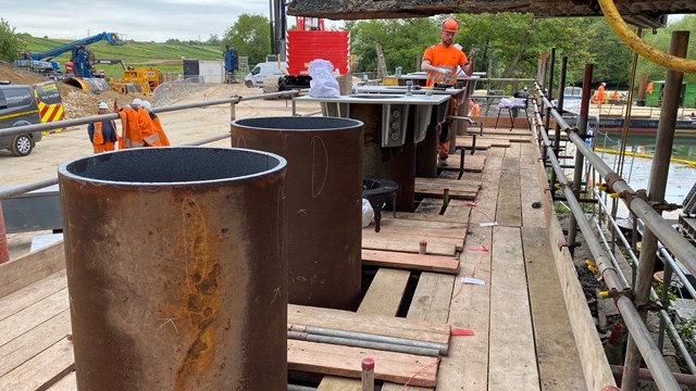
One of the pile caps can be seen in the Network Rail media photo to hold the cill beam, with viaduct above

The repair of the viaduct is complex, challenging and requires some heavy engineering:
  • 24 x 15m long steel piles have been driven into the bed of the River Thames to create a solid platform for the temporary structure that is currently holding the weight of the viaduct.
  • A 750-tonne crane was used to lift the temporary structure into place.
  • 3,000m3 of material has been removed from the embankment to create space to build a new abutment.
  • Eight more piles have been driven up to 20m into the embankment to support the new structure.
Working on the piles at Nuneham viaduct.jpg
 
Last edited:

ThickMike

New Member
Joined
6 Apr 2023
Messages
4
Location
Banbury
Well I am no Civils expert but it looks to me as though they - that is NR and all their sub-contractors - are making as good a job of this as could be reasonably hoped for or expected. Of course there is a "yes, but" discussion to come - why didn't they spot the problem, identify the options, de-risk the situation earlier to avoid the immense disruption that this has caused but i'm happy to wait for those answers. The NR video gives confidence about progress, that they know what they are doing and recognise what bad neighbours they have been for the last two months. The outturn of this for me is to wonder how many other Nuneham viaducts there are waiting to happen, and whether NR need to modify, and get support for, their maintenance activities in the future understanding that our climate looks less predictable than ever in the past.
All the best, Mike

 

Nicholas Lewis

Established Member
Joined
9 Aug 2019
Messages
8,024
Location
Surrey
Well I am no Civils expert but it looks to me as though they - that is NR and all their sub-contractors - are making as good a job of this as could be reasonably hoped for or expected. Of course there is a "yes, but" discussion to come - why didn't they spot the problem, identify the options, de-risk the situation earlier to avoid the immense disruption that this has caused but i'm happy to wait for those answers. The NR video gives confidence about progress, that they know what they are doing and recognise what bad neighbours they have been for the last two months. The outturn of this for me is to wonder how many other Nuneham viaducts there are waiting to happen, and whether NR need to modify, and get support for, their maintenance activities in the future understanding that our climate looks less predictable than ever in the past.
All the best, Mike
NR were well aware of the deteriorating situation and were attempting to manage it to avoid closure but on this occasion the various interventions they tried failed to achieve a satisfactory outcome. Id wager that if they had gone to operators to say we need close this line for months they would have been told to come back in 2-3 years. However, in some respects there is nothing like a crisis on the railways to get things done and the industry has done itself proud here in both coming up with a technical solution but also in putting in the necessary alterations to services to deal with the loss of the route. Gives me comfort that the can do attitude is still there.
 

Pigeon

Member
Joined
8 Apr 2015
Messages
1,123
I suspect that the act of drilling holes into the foundations to inject the strengthening polymer solution might have been the final straw that tipped it over the edge.

I wondered that myself when I heard they had tried that. It's one of those methods that is attractive because it's so much easier than anything else, and if the conditions are right it can be remarkably effective. The odd bits of research I've read about it make that same emphasis in considerably more detail, and make it clear that the condition and type of ground and its previous history of instability are major influences on whether grouting will be effective at all and on what type of grout and what procedure need to be used... and also that if the conditions are not right, it may just do nothing, or it may make things worse either acutely or chronically. I get the impression that it is often applied to real situations where they have far less knowledge of the conditions than is possible in a research setting, and inadvertently triggering acute instability is consequently something that happens more often than it should.

However it doesn't sound like that's the case here; it sounds more like the ground was never great in the first place, and has just naturally got worse over the years until it's got to the point where grouting simply won't do anything at all either way, and things will carry on collapsing in an unchanged manner until you do something at least reasonably drastic.
 

DelW

Established Member
Joined
15 Jan 2015
Messages
6,021
One of the pile caps can be seen in the Network Rail media photo to hold the cill beam, with viaduct above


View attachment 135722
That's an unusual pile cap detail - I've seen quite a few pile caps and piled abutments and I've never seen one that looked anything like that. The shear design would be interesting, I'm guessing it must be done according to the steel rather than concrete code to use those bolted connections. Innovative design by someone! The holes in the capping plates suggest that the piles may be filled with concrete before or possibly during the abutment pour.

There have certainly been some unusual challenges and solutions on this job, it's kept me guessing throughout. I hope someone involved will produce a technical paper explaining it all once the metaphorical dust has settled
 

Nicholas43

Member
Joined
16 Jun 2011
Messages
652
Location
Radley
Have they said whether they will add sticky-out prongs (to use the technical term ...) to the span, to rest on the stuff now resting on the pile caps?
 
Status
Not open for further replies.

Top