Our new ticketing site is now live! Using either this or the original site (both powered by TrainSplit) helps support the running of the forum with every ticket purchase! Find out more and ask any questions/give us feedback in this thread!
I have looked through all previous threads re Lelant Station and have not found anything to help solve this mystery.
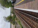
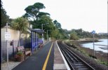
i have a picture, taken this week, of the station showing two lengths of normal rail bolted down onto the (concrete ?) sleepers, bur showing no sign of use as they are oxidised (similar to rail lengths that laid about waiiting for future use.
i have described all this in case I am unable to attach the jpg. Image
Trust that someone may be able to throw some light on this. Thanks.
They've certainly been connected to those steel sleepers since the 2016 relay through there - I did think it could be to do with the track stabilising given the location on the riverbank.
However, they look way too far from the running rails for that. Check-rails are usually much closer to the running rails (stand to be corrected though).
However, they look way too far from the running rails for that. Check-rails are usually much closer to the running rails (stand to be corrected though).
They've certainly been connected to those steel sleepers since the 2016 relay through there - I did think it could be to do with the track stabilising given the location on the riverbank.
Thank you all very much for your prompt replies, all of which seem likely scenarios - bot I woUtd just like to pick up on ‘davetheguard’s point.........“in the event of a derailment, to stop the train bursting through the parapet and over the side.......Could this have the same intention; but in this case to stop a derailed train ending up in the estuary?”
I would enlarge the last sentence to say “but in this case to stop a derailed train ending up in the estuary or onto the platform”
There’s a fixed distant in the far end of the photo - presumably the AWS cancel sign is for trains passing over the fixed distant’s magnet in the other direction.
There’s a fixed distant in the far end of the photo - presumably the AWS cancel sign is for trains passing over the fixed distant’s magnet in the other direction.
Aha. But there’s no AWS magnet in the picture, nor in a picture I’ve found elsewhere (attached, not mine). But there is bonding on the ‘guard rails’. Perhaps the guard rails are, for some reason, the AWS permanent magnet? Very odd.
However in other photos I’ve found that St Andrew’s cross was there when the guard rails weren’t... curious. I’m stumped! Paging @MarkyT who knows about these things...
Edit: just found a video on you tube of a ‘station tour’, and you can see the AWS permanent magnet on the St Erth side of the crossing. So the guard rails are not an AWS substitute. I’m going back to Guard rails.
Aha. But there’s no AWS magnet in the picture, nor in a picture I’ve found elsewhere (attached, not mine). But there is bonding on the ‘guard rails’. Perhaps the guard rails are, for some reason, the AWS permanent magnet? Very odd.
However in other photos I’ve found that St Andrew’s cross was there when the guard rails weren’t... curious. I’m stumped! Paging @MarkyT who knows about these things...
Edit: just found a video on you tube of a ‘station tour’, and you can see the AWS permanent magnet on the St Erth side of the crossing. So the guard rails are not an AWS substitute. I’m going back to Guard rails.
I saw some other photos of this years recent work, (in a different forum), showing identical guardrails in the St Ives station approach, which are doing the usual job as the railway passes over a low viaduct.
Definitely guard rails, as usually found on bridges. As for the AWS, there is a yellow magnet visible on Google Earth aerial photos, and in that first image I think it's hiding in the vegetation between the rails. The cancelling indicator method of dealing with AWS on branch lines allows an unsuppressed permanent magnet only to be used, which has no power or control cabling requirements. On low speed branches, spacing between a magnet and the board(s) or signals it applies to may be significantly less than the default circa 200m dimension used on main lines. Standards allow the dimension to be adjusted within consistent timing constraints where this is expedient.
== Doublepost prevention - post automatically merged: ==
I doubt there is bonding as there is unlikely to be any track circuits that far out of St Erth. The line is worked under authority of a train staff, and being diesel operated there's no need for any traction return bonding. Sometimes branches and sticks on the track can look a bit like bonding cables.
Oddly enough I was wasting my evening passing some time watching stuff on YouTube and happened upon a cab ride on the Tyne and Wear metro, and the guard rails on the bridge of the Tyne are the same as in the Lelant photo - no tapering at the ends and further from the running rails than I remember.
For the avoidance of doubt, a check rail is very close to a running rail, normally the inner rail on a tight curve or opposite the rail gap in pointwork. If the wheels start moving outwards, the back of the flange of the inner wheel contacts the check rail before the other flange can get far enough to climb over its own rail. These aren't check rails.
As various people have mentioned or implied, a guard rail is provided where, if a derailment happens for any reason, there is unusual hazard such as the risk of going off a bridge with no solid parapet. The guard rail is further from the running rails, occasionally outside them, and positioned to catch a wheel before the opposite wheel encounters the hazard.
I don't think these are guard rails. There doesn't seem particularly more hazard on this section than on the rest of the track visible in the photo, and the guard rail further from the platform doesn't address any hazard - striking the platform is no more probable here than any other platform and if they were to protect against that then they'd start before the beginning of the platform.
I agree with the suggestion that there is some risk of the formation being undermined here, possibly due to proximity to the sea, and these provide some protection against the rails sinking into the gap and creating a derailment risk.
It seems unlikely that they are guard rails - if they were, why would they stop before the embankment does? Feels more likely that they're to improve the integrity of the track in some way - perhaps related to them stopping at the end of the platform structure.
Edit: edwin_m has already said this with better detail!
They should increase the stiffness of the track in the locality. I agree they make little sense as guard rails in the traditional sense of derailment containment here, but they probably used the same standard design for another purpose.
I note the steel sleepers have a selection of "extra" holes, some of which coincide with the fixings for the "guard" rail, although they're only used on alternate sleepers. Not sure if these are standard provision on steel sleepers (IIRC they use some holes for lifting them) or if there's a special version for this kind of situation.
The holes in the sleepers are indeed specific fastening locations for guard rails. Steel sleepers are normally supplied without these holes but they can be ordered with them where it's inteneded to fit guard rails.
To mostly echo what others have said, rails in the 4ft like these are commonly used for either derailment protection (to constrain the trajectory of a derailed train, not prevent it derailing in the first place) and/or stiffness enhancement.
I don't know the site but from aerial mapping and can see no specific reason why the risks of derailment here are high enough to warrent guard rails, and thus assume they are purely for the latter. This would be supported by the omission of 'gathering' or 'butterfly' rails at the ends fo the guard rails. If they were there to mitigate derailments there would nortmally be a set of splayed rails at the start to 'catch' a derailed train and bring it back to a controlled position.
The track here appears to be (from a LIDAR survey) approx 1.5-2m above high tide level, so the formation will almost certainly be affected by changes in groundwater levels with the tides. Whilst I have no direct experiance with this site, I know of track monitoring in some places near the sea which has given results of around a 10mm difference in track level between high and low tides. Sounds bad but as it's gradual and uniform and it's the whole formation that's lifting and settling it's not really a big issue.
The formation here is likely to be quite soft and thus have a low stiffness value, which could present issues with differential settlement and poor vertical alignment, or 'top'. Overall track stiffness as experianced by a train is a result of many factors, one of which is the stiffness of the rail itself and one of which is the ability of the sleepers to distribute the load.
I note that this track had timber sleepers before the renewal, without these additional rails. Timbers weigh more than steels and also offer a small amount of compressability or 'give', contributing to improved track performance. Their replacement with steel meant the sleeper weight went down and this flexibility was lost, and also that the ability of the sleepers to spread the load to the ballast was reduced, increasing the point loading on the ballast and increasing the potential for settlement.
Adding the central two rails increses the stiffness of the track, mitigating this loss, and also meaning any localised settlement will have a lesser effect as the track is better able to 'span' any small areas with lesser load support.
With soft formation and low track stiffness you also have to be careful of something called a "Rayleigh wave" which can develop if the train is travelling at or near the "Critical Velocity" of the ground. This effect is dependant on the stiffness of the track and formation and the speed of the trains, and can cause derailments in a worst case scenario.
Another additional benefit is that the additional rails also provide an increase in lateral resistance, meaning that horizontal alignment is generally improved, the track has greater ability to resist thermal and dynamic forces and thus buckling, and if needed it has the potential for a slightly higher 'Critical Rail Temperature' to be applied (although this is not specified in standards and would have to be done via local agreements with the maintainer).
== Doublepost prevention - post automatically merged: ==
Definitely guard rails, as usually found on bridges. As for the AWS, there is a yellow magnet visible on Google Earth aerial photos, and in that first image I think it's hiding in the vegetation between the rails. The cancelling indicator method of dealing with AWS on branch lines allows an unsuppressed permanent magnet only to be used, which has no power or control cabling requirements. On low speed branches, spacing between a magnet and the board(s) or signals it applies to may be significantly less than the default circa 200m dimension used on main lines. Standards allow the dimension to be adjusted within consistent timing constraints where this is expedient.
== Doublepost prevention - post automatically merged: ==
I doubt there is bonding as there is unlikely to be any track circuits that far out of St Erth. The line is worked under authority of a train staff, and being diesel operated there's no need for any traction return bonding. Sometimes branches and sticks on the track can look a bit like bonding cables.
As for bonding, I can't see any bonding in the photos and can't see any need for bonding of the guard rail. They would be bonded in an electrified area, but this clearly isn't one, so probably just branches or something giving an optical illusion.
As for bonding, I can't see any bonding in the photos and can't see any need for bonding of the guard rail. They would be bonded in an electrified area, but this clearly isn't one, so probably just branches or something giving an optical illusion.
Another additional benefit is that the additional rails also provide an increase in lateral resistance, meaning that horizontal alignment is generally improved, the track has greater ability to resist thermal and dynamic forces and thus buckling, and if needed it has the potential for a slightly higher 'Critical Rail Temperature' to be applied (although this is not specified in standards and would have to be done via local agreements with the maintainer).
If the radius is below 350m and the track is CWR then the additional rails are in place of the yellow lateral resistance plates that would be fitted to concrete and timber sleepers as they are not compatible with steels.
I’ve never known anything other than running rails (and rails associated with crossings and points) to have track circuit bonding attached.
Sometimes where there are points that have electric point heating, you may find temperature probes attached to what appear to be random rails. But that is obviously not the case here.
I suspect what you are seeing is bits of twig that look like cables.
In a rural area where there is not much signalling, it’s not unknown for location cases (equipment cupboards)on station platforms to be provided for telecommunications cables, for signalling lineside cable terminations, or for the station electrical supply for the lighting etc.
They are less likely to be associated with track circuits, as normally you would not have two different track circuits abutting and the required IRJs in the area of the platform unless the layout is tight for space.
We are aware of an issue with emails from the Forum to Microsoft-based email accounts (hotmail/outlook/live.com email addresses). This is being looked into currently, thanks for your patience meanwhile.