Our new ticketing site is now live! Using either this or the original site (both powered by TrainSplit) helps support the running of the forum with every ticket purchase! Find out more and ask any questions/give us feedback in this thread!
I'd suspect that the wider track gauge (5ft 6in) is the real stability factor. Also, the 5-car double-stack sets have a lower platform than other I.R. container wagons. The special e-lok pantographs do have a very high reach, maybe more than any of the US e-loks?
As far as I know no US electrics can be used with double stack containers.
A Mexican railway took down their electrification to allow double stack containers to run on one of their main lines.
An interesting topic. At Guide Bridge Station, the overhead wiring comes well down to clear Guide Lane bridge, pantographs are nearly flat. Still in use at 25kV.
I can remember in the 1960's , the platform water columns were still working , at least one of them on platform 2 very close to the bridge, there cannot have been much safe headroom when watering a steam loco, though it is possible its use was restricted to side tank engines, slightly more safe. The columns were there for many years after steam went, complete with brazier basket to keep frost at bay . The level crossing at Dinting Lane had the wiring at a maximum height , possibly due to the way the road approaches the railway.
I remember being at the 'old station' and walking down the steps. I'm fairly tall and I reckoned I could jump up to touch the OLE above the steps, although that section I'm most certain wasn't live. It was removed after the AC conversion.
I don't know the answer to the question but I do have doubt about some of the suggestions. The high clearance was very noticeable. On the way into Wath shed in the 60's I took the attached photo - it's a dead end stabling siding but the clearance is still massive - certainly didn't occur only at level crossings.
The earlier 1500V D.C. electrification with an LNER involvement was the MSJ&A and I'm trying to remember details of that. Here's a photo I took bunking Altringham depot, and it's noteable because not only does the clearance also seem high, but it shows that Stone-Faiveley pans could also accommodate the height - a few of the units had their original diamond pans replaced.
When the MSJ&A line was being converted to AC standards, the old pantographs couldn't cope with the new overheads, (not volts / currents, just the physical alignments), all the surviving units were fitted with compatible pantographs. I remember watching a 6-car set arriving at Oxford Road back in 1961 & being surprised that the two systems were so close to each other.
Of course, what's left of the original system is now feeding 750v DC to the Metrolink trams with help from the (now insulated) AC return wires to reduce voltage drop.
It was interesting from Inversnecky 'film clip' that Indian Railways are using double-stack containers. In my naivety, I thought it was only the USA that had them. Does any other country in the world use double-stacks? I'd be interested to hear. Thanks
I can recall reading somewhere that signal sighting was the reason why the wires were so high.
The masts etc would have obscured the existing semaphore signals.
I'd suspect that the wider track gauge (5ft 6in) is the real stability factor. Also, the 5-car double-stack sets have a lower platform than other I.R. container wagons. The special e-lok pantographs do have a very high reach, maybe more than any of the US e-loks?
The North American-style double-stacks in well/pocket wagons are rather more stable than you might think. I've seen a few double-stack trains going slowly/stopped on super-elevated (canted) curves and whilst the 'lean' can be quite noticeable in that situation, due to the low centre-of-gravity they don't fall over easily.
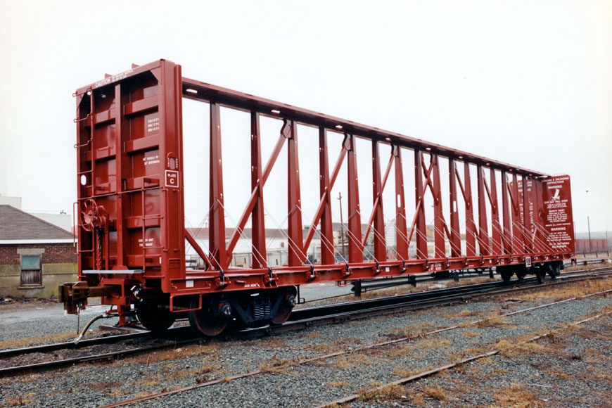
Centre-beam lumber (timber) cars are probably some of the worst freight cars for stability when empty, due to their relatively light tare weight combined with their height e.g.:
The North American-style double-stacks in well/pocket wagons are rather more stable than you might think. I've seen a few double-stack trains going slowly/stopped on super-elevated (canted) curves and whilst the 'lean' can be quite noticeable in that situation, due to the low centre-of-gravity they don't fall over easily.
Centre-beam lumber (timber) cars are probably some of the worst freight cars for stability when empty, due to their relatively light tare weight combined with their height e.g.:
I think the text visible but not legible on the far end of that wagon is a warning against uneven loading for that very reason. I believe North American style freight trains including double stack are run at significantly lower maximum cant deficiency than European ones.
According to the FRA rules, normal curving limits are: 7 inches of superelevation, 3 inch cant deficiency, and any wheel is not allowed to unload to less than 60% of its static load on level track.
Operating at higher cant deficiency (I assume primarily for passenger operations) is allowed but has to be specifically approved by the FRA.
I don't know how this compares to normal European & UK standards.
Another interesting article with some photos, eg of the castellated station at the West end of the tunnel demolished to make space for a new tunnel, as the existing ones weren’t high enough to incorporate the overhead lines.
Reading these posts made me think of how much current there was for each pantograph over 500 amps dc! No wonder they were of such large construction and very unsightly.
They must have system voltage drop problems.
Of course, what's left of the original system is now feeding 750v DC to the Metrolink trams with help from the (now insulated) AC return wires to reduce voltage drop.
The Metrolink Altrincham line was completely rewired in 2009, to tramway 750V standards. The original mast and portal structures were retained, but with new catenary, insulators, cantilevers, registration arms etc.. The system is now auto-tensioned in place of the original fixed termination design, and double insulated as required on tramways.
Metrolink does use parallel feeders to reduce volts drop between substations, and on parts of the network the contact wires are doubled.
I believe the 25kV conversion of Ardwick to Glossop/Hadfield was done over a weekend as minimum change, just insulators and contact wires, and much of the rest of the original 1500V equipment is still in use today. It is a fixed termination system (sags in hot weather), with a third messenger wire between the catenary and contact wires.
The Metrolink Altrincham line was completely rewired in 2009, to tramway 750V standards. The original mast and portal structures were retained, but with new catenary, insulators, cantilevers, registration arms etc.. The system is now auto-tensioned in place of the original fixed termination design, and double insulated as required on tramways.
Metrolink does use parallel feeders to reduce volts drop between substations, and on parts of the network the contact wires are doubled.
I believe the 25kV conversion of Ardwick to Glossop/Hadfield was done over a weekend as minimum change, just insulators and contact wires, and much of the rest of the original 1500V equipment is still in use today. It is a fixed termination system (sags in hot weather), with a third messenger wire between the catenary and contact wires.
The MSW & GE electrifications were very similar, probably LNER designed albeit finished by British Railways.
I'm staying in Essex & nearly all of the original GE system has been upgraded to auto-tension with many new structures, but with some of the original portal masts still in use. There's quite a variety of OHLE in the current GE / Anglia system, as is also on the LT&S route, some of which was incorporated into the original GE scheme @ 1.5 kV DC. (Bow Junction to Fenchurch Street.).
== Doublepost prevention - post automatically merged: ==
Reading these posts made me think of how much current there was for each pantograph over 500 amps dc! No wonder they were of such large construction and very unsightly.
They must have system voltage drop problems.
There are quite a few Youtube cab-ride videos of the Dutch (NS) 1.5 kV DC system, well worth viewing. Some of the recent changes (new routes & multiple tracking, etc.) include provision for changing to 25kV AC, (bigger insulators) but currently using the high voltage feeder cables (intended to be @ 50 kV AC?) connected to the DC catenary, probably to reduce voltage drop.
The NS standard system has more copper in the air than in the UK, always twin contact wires + at least one feeder cable per track.
They do run longer & heavier electric passenger trains, especially the older Hondekop emu's up to 14 car rakes , (2-car set =104 tons, 4-car set = 206 tons). + 4K ton iron-ore freights .
I believe the 25kV conversion of Ardwick to Glossop/Hadfield was done over a weekend as minimum change, just insulators and contact wires, and much of the rest of the original 1500V equipment is still in use today. It is a fixed termination system (sags in hot weather), with a third messenger wire between the catenary and contact wires.
As with the conversion of the GEML 1500v D.C. system, there’s is a load of work done in advance; the changeover itself is fairly simple.
All the really needs to change in the OLE is the insulators and their associated registration arms, and because the voltage is going up that can be done at any time in advance. The contact wire usually remains (I’ve posted elsewhere a pic of original 1949 contact wire from the GEML that was removed in 2011).
All the new AC distribution kit is built and tested in advance whilst the D.C. is still operating; this includes all the revised return current arrangements and any necessary signaling changes.
‘All’ that happens at changeover is that the D.C. distribution is decommissioned (a flick of a switch and some bus bars being removed), the AC distribution is connected to the grid feeders and commissioned (a more complex process), everything trackside is checked, and away you go. The more difficult part of the process is getting all the D.C. trains off the network and the new AC trains on. This is what took the time for the GEML switch over as the existing stock was modified. IIRC whilst the electrification was swapped over in a long weekednd, there were reduced services for weeks if not months either side as stock was withdrawn for modification.
All the really needs to change in the OLE is the insulators and their associated registration arms, and because the voltage is going up that can be done at any time in advance. The contact wire usually remains (I’ve posted elsewhere a pic of original 1949 contact wire from the GEML that was removed in 2011).
A post in a previous thread in 2011 suggested that the contact wire was replaced when the Glossop/Hadfield line was converted to 25kV:
electra27000 said:
I can't comment on the Altrincham line conversion, but work on the conversion of the Hadfield/Glossop line started in the Spring of 1984, with the gradual replacement of all the insulators with 25kV ones. I also seem to recall that the actually conversion work, over that weekend in December 1984, involved stripping out all the old DC contact cabling and replacing it with the AC version. It's actually said that the scrap value of the thicker DC cabling meant BR made money by converting the line to AC!
As with the conversion of the GEML 1500v D.C. system, there’s is a load of work done in advance; the changeover itself is fairly simple.
All the really needs to change in the OLE is the insulators and their associated registration arms, and because the voltage is going up that can be done at any time in advance. The contact wire usually remains (I’ve posted elsewhere a pic of original 1949 contact wire from the GEML that was removed in 2011).
All the new AC distribution kit is built and tested in advance whilst the D.C. is still operating; this includes all the revised return current arrangements and any necessary signaling changes.
‘All’ that happens at changeover is that the D.C. distribution is decommissioned (a flick of a switch and some bus bars being removed), the AC distribution is connected to the grid feeders and commissioned (a more complex process), everything trackside is checked, and away you go. The more difficult part of the process is getting all the D.C. trains off the network and the new AC trains on. This is what took the time for the GEML switch over as the existing stock was modified. IIRC whilst the electrification was swapped over in a long weekednd, there were reduced services for weeks if not months either side as stock was withdrawn for modification.
I was taking notice of just what had to be done to the original GE network DC to AC change in 1960 (all in one weekend) & the original insulators were retained, it seems that 6.25 kV AC didn't require any changes. The much later change-over to 25 kV AC was spread over small sections of the route. As for rolling stock, some of the the 306's were modified before the change-over, but the already-built but not yet required LT & S 302's were made available to cover. They were also used (in 3-car formations) to cover for the unreliable 305's on the Chenford inner suburbans.
Another interesting article with some photos, eg of the castellated station at the West end of the tunnel demolished to make space for a new tunnel, as the existing ones weren’t high enough to incorporate the overhead lines.
Actually that wasn't true, the LNER planned to use the original tunnels and wire right through them.
Pages 88-89 of E M Johnson's 'Woodhead - The Electric Railway' have two photos of the Woodhead portals of the original single bore tunnels, one of which is dated 1950. They both show OLE gantries - which were erected before WW2 - running right up to the old portals. Subsequently the linings of the old tunnels were found to be in such a bad state that any plan to use them for electrification was abandoned and the new tunnel was constructed.
== Doublepost prevention - post automatically merged: ==
The MSW & GE electrifications were very similar, probably LNER designed albeit finished by British Railways.
I'm staying in Essex & nearly all of the original GE system has been upgraded to auto-tension with many new structures, but with some of the original portal masts still in use. There's quite a variety of OHLE in the current GE / Anglia system, as is also on the LT&S route, some of which was incorporated into the original GE scheme @ 1.5 kV DC. (Bow Junction to Fenchurch Street.).
== Doublepost prevention - post automatically merged: ==
There are quite a few Youtube cab-ride videos of the Dutch (NS) 1.5 kV DC system, well worth viewing. Some of the recent changes (new routes & multiple tracking, etc.) include provision for changing to 25kV AC, (bigger insulators) but currently using the high voltage feeder cables (intended to be @ 50 kV AC?) connected to the DC catenary, probably to reduce voltage drop.
The NS standard system has more copper in the air than in the UK, always twin contact wires + at least one feeder cable per track.
They do run longer & heavier electric passenger trains, especially the older Hondekop emu's up to 14 car rakes , (2-car set =104 tons, 4-car set = 206 tons). + 4K ton iron-ore freights .
Yes, both MSW and the initial GE DC electrification were designed by the LNER and completed by British Railways. I believe that the main contractor for the OLE was British Insulated Callender's Cables (BICC - now Balfour Beatty).
The GE Liverpool St-Shenfield scheme went live in 1949, with Shenfield-Chelmsford and Shenfield-Southend Vic in 1956 (all at 1500V DC). The MSW was implemented in stages during the 1950s.
The section from Fenchurch St to Bow Junction on the GE was also part of the 1949 electrification. Intended as a diversionary route for electrics if Liverpool St was closed, there were originally plans to run an EMU shuttle from the west facing bay platform at Stratford to Fenchurch St but this was never implemented. Only the slow lines (now the DLR) between Stepney East (Limehouse) and Fenchurch St were originally electrified. From what I've read, the only time the section saw electric passenger working under DC was during the 1953 floods when the LT&S was closed between Benfleet and Leigh on Sea. In 1961 it was converted to 6.25kV AC and AC electric working on the LT&S began in 1962.
I'd suspect that the wider track gauge (5ft 6in) is the real stability factor. Also, the 5-car double-stack sets have a lower platform than other I.R. container wagons.
I believe the 25kV conversion of Ardwick to Glossop/Hadfield was done over a weekend as minimum change, just insulators and contact wires, and much of the rest of the original 1500V equipment is still in use today. It is a fixed termination system (sags in hot weather), with a third messenger wire between the catenary and contact wires.
Some good photos at the link below, and reference to the use of two pantographs by 76s:
“The EM1's had worked 'one pan up' on test freights on the Ilford - Shenfield line before the Woodhead route was opened to the electrics. Two 'pan' running would be necessary on the Woodhead route because the OLE did not have auto (wheel) tensioners, there were problems with contact wire stability.”
We are aware of an issue with emails from the Forum to Microsoft-based email accounts (hotmail/outlook/live.com email addresses). This is being looked into currently, thanks for your patience meanwhile.







 )
)