
• Our new ticketing site is now live! Using either this or the original site (both powered by TrainSplit) helps support the running of the forum with every ticket purchase! Find out more and ask any questions/give us feedback in this thread!

“Along track conductor” question.

King Lazy

Member
Joined
24 Apr 2019
Messages
152
I’d like to ask a question of those knowledgeable in electrification.

Put simply how dangerous is the “Along track conductor” wire and what does it actually do.

I have always known it as the ‘return conductor’ as that was what it was called when I first started my career.

In the rule book this wire is shown as red the same as all the other OLE wires.

I’ve heard many things from non engineers ranging from it is 25kv when a train is in section to it completes the electrical circuit.

But my interest has been piqued by seeing parts of it apparently (to my untrained eye) not exactly out of reach. I understand no engineer would leave something obviously unsafe but.

I’ve seen a portion of it that collapsed tied to a fence and left like that for some time.

A portion hanging very low where a trespasser could walk into it in the dark (I reported this but it seemed not to have been urgently repaired but was put back up after a day or so).

A portion at a major station running across a metal girder on a footbridge with apparently no insulation (wire clearly bare).

And the other day a portion attached to a signal with what looked like a very small insulator rather than the standard size ones we see on registration arms.

I remember as a boy of around 8 being at a station and seeing a wire very close to the footbridge steps as we went down though probably just out of reach of someone leaning over.

So I’d be grateful for a simple-ish explanation as to what it does and how dangerous it is (not that I’m planning on touching it!).
 
Sponsor Post - registered members do not see these adverts; click here to register, or click here to log in
R

RailUK Forums

Elecman

Established Member
Joined
31 Dec 2013
Messages
3,567
Location
Lancashire
I’d like to ask a question of those knowledgeable in electrification.

Put simply how dangerous is the “Along track conductor” wire and what does it actually do.

I have always known it as the ‘return conductor’ as that was what it was called when I first started my career.

In the rule book this wire is shown as red the same as all the other OLE wires.

I’ve heard many things from non engineers ranging from it is 25kv when a train is in section to it completes the electrical circuit.

But my interest has been piqued by seeing parts of it apparently (to my untrained eye) not exactly out of reach. I understand no engineer would leave something obviously unsafe but.

I’ve seen a portion of it that collapsed tied to a fence and left like that for some time.

A portion hanging very low where a trespasser could walk into it in the dark (I reported this but it seemed not to have been urgently repaired but was put back up after a day or so).

A portion at a major station running across a metal girder on a footbridge with apparently no insulation (wire clearly bare).

And the other day a portion attached to a signal with what looked like a very small insulator rather than the standard size ones we see on registration arms.

I remember as a boy of around 8 being at a station and seeing a wire very close to the footbridge steps as we went down though probably just out of reach of someone leaning over.

So I’d be grateful for a simple-ish explanation as to what it does and how dangerous it is (not that I’m planning on touching it!).
I think your confusing Return Conductors for Ariel Earth conductors
 

King Lazy

Member
Joined
24 Apr 2019
Messages
152
I’ve just looked that up as I’d never heard of the term. I think you are correct.

I have always just assumed any wire running along the cess side of the structure was a return conductor but I’ve just seen a diagram showing both one over the other. Return conductor and what is marked “earth wire” underneath.

I’m still slightly confused as most places I can think of have a basically symmetrical set up with the catenary and contact wires above the four foot and a larger wire running down the outside of the structures on the cess side either side of the formation.

It is this that I have always assumed to be the return conductor as it appears to match the rule book diagram.

Edit. More confusingly I’ve now seen a diagram that implies they’re the same thing?

== Doublepost prevention - post automatically merged: ==

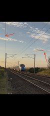
I’ve marked on this picture what I always took to be the “return conductor” now renamed the “along track conductor” if my rules knowledge is correct.
 

Attachments

  • IMG_8907.jpeg
    IMG_8907.jpeg
    257.4 KB · Views: 101
Last edited:

Albaman

Member
Joined
16 Sep 2018
Messages
131
I don't want to go too far off topic but " King Lazy" has raised some points here which intrigue me.

In days gone by, on tracks electrified with the 25kV overhead system, each structure had an earth bond connecting it to one of the rails and at locations, no doubt at standard distances apart, there were bonds ( known at one time as " red bonds " ) which connected the rail to a return conductor wire which was connected to and insulated from the structure. Also, at what were specified distances, booster transformers were attached to the structure.

I have noticed in more recent schemes, as illustrated in the photo, there is no return conductor and , instead structures are connected by a wire, the connection for which is not insulated from the structure ( to be pedantic, on my recently electrified route , there are one or two structures which have a bond direct to the rail ).

I've noticed there are wires with black covering between the rails and the wire mentioned above. Also , at certain locations, cables are linked to the rail and pass through a box marked " Traction Bonds " .

Apologies for the lack of precise terminology , but I am curious why booster transformers are no longer installed and the " destination " of wires that pass through the " Traction Bond " boxes.
 

PartyOperator

Member
Joined
26 May 2019
Messages
190
Sounds like you're noticing the difference between traditional 25kV OHLE and the newer 2x25kV autotransformer system. With 2x25kV there's a negative feeder out of phase with the catenary so power is transmitted at 50kV. Booster transformers aren't needed.
 

swt_passenger

Veteran Member
Joined
7 Apr 2010
Messages
34,227
Sounds like you're noticing the difference between traditional 25kV OHLE and the newer 2x25kV autotransformer system. With 2x25kV there's a negative feeder out of phase with the catenary so power is transmitted at 50kV. Booster transformers aren't needed.
But surely if the anti-phase feed was being carried at a high level on those masts wouldn’t it be fitted with 25kV insulators?
 

OLEngineer

Member
Joined
10 Jun 2026
Messages
16
Location
London
I don't want to go too far off topic but " King Lazy" has raised some points here which intrigue me.

In days gone by, on tracks electrified with the 25kV overhead system, each structure had an earth bond connecting it to one of the rails and at locations, no doubt at standard distances apart, there were bonds ( known at one time as " red bonds " ) which connected the rail to a return conductor wire which was connected to and insulated from the structure. Also, at what were specified distances, booster transformers were attached to the structure.

I have noticed in more recent schemes, as illustrated in the photo, there is no return conductor and , instead structures are connected by a wire, the connection for which is not insulated from the structure ( to be pedantic, on my recently electrified route , there are one or two structures which have a bond direct to the rail ).

I've noticed there are wires with black covering between the rails and the wire mentioned above. Also , at certain locations, cables are linked to the rail and pass through a box marked " Traction Bonds " .

Apologies for the lack of precise terminology , but I am curious why booster transformers are no longer installed and the " destination " of wires that pass through the " Traction Bond " boxes.
Some areas are electrified with an RC systems usually including Booster Transformers, whilst others are electrified using a 2x25kV ATF system. Both systems describe how current returns to the feeder station, with ATF systems being more efficient than RC systems, allowing for greater spacing between feeder stations and money saved. New booster transformer return conductor systems shall not be installed unless prior agreement with NR Technical Head for AC/DC systems!

There are also multiple ways to bond an OLE structure to earth/traction return circuit. An aerial earth wire can be used, or bonds can be connected on the ground or through troughing to a spider plate which is connected to the traction return circuit. The bonds that connect to a spider plate from an OLE structure are covered with the black box cover marked "Traction Bond", hiding a plate which the bonds are connected to. OLE structures with switches require 2 connections to the traction return circuit, for example.

1783338242859.png
See picture above of bonding connections covered by a "traction bonds" box. Other assets can be bonded to the OLE structure to inadvertently bond it to earth.

Technically, earth wire forms a part of the traction return circuit which sends return current from the train back to the feeder station. However, RC cable and Earth Wire cable are different in practice as RC is insulated from earth so that the current flowing through the cable can interfere and reduce the magnetic fields generated by the OLE. See below photo from Garry Keenor's Overhead Line Electrification for Railways 6th Edition. A booster transformer can be added to increase the level of current in the RC and therefore cancel out a greater proportion of the OLE magnetic field. This immunisation role is better carried out by ATF.

1783339000707.png
 

Top